Authored by SK&A Principal Justin Long, PE, RBEC, BECxP. Follow Justin on Linked In.
Continuity, Dew-Point Control, and the Risks of Getting It Wrong
In recent Enclosure Insights posts, we have traced the primary mechanisms by which moisture enters, moves through, and accumulates within building enclosure assemblies — from bulk water infiltration and humidity-driven condensation to air leakage and enthalpy recovery. Running alongside all of these mechanisms is a factor that simultaneously governs energy performance, occupant comfort, and moisture risk: thermal control.
Insulation is the primary tool for delivering thermal control. But insulation is not simply about R-value. Where insulation is placed, how continuous it is, and how it interacts with the assembly’s air, vapor, and water control layers determines whether it performs as intended — or inadvertently creates the conditions for failure. This month’s Enclosure Insights examines the principles of high-performance insulation: thermal continuity, dew-point control, code requirements, and the underappreciated risks of over-insulating.
Why Thermal Continuity Matters
Thermal performance is not simply a function of the total R-value specified within an assembly. It is a function of how continuously that R-value is maintained across the full building enclosure — walls, roofs, foundations, transitions, and all interfaces between them.
When insulation is interrupted — by framing members, structural penetrations, slab edges, parapets, or transitions between assembly types — heat flows preferentially through the path of least resistance. These interruptions, known as thermal bridges, can dramatically reduce the effective R-value of an assembly relative to its nominal R-value. (Thermal bridging and its mitigation will be the focus of next month’s Enclosure Insights.)
Beyond energy performance, thermal continuity is directly tied to condensation risk. Cold surfaces within or on the interior face of enclosure assemblies can reach the dew point of interior air, producing condensation, moisture accumulation, and long-term degradation. A continuous thermal envelope keeps these cold surfaces on the exterior side of the control layers — where condensation, if it occurs, can drain or dry rather than accumulate within the assembly.
Insulation and Dew-Point Control
One of the most critical — and least understood — roles of insulation in enclosure design is its influence on where the dew point occurs within an assembly. As discussed in prior installments, condensation occurs when a surface within an assembly drops to or below the dew point temperature corresponding to the moisture content of the air in contact with it.
The location of insulation within an assembly determines the temperature gradient across its layers. By placing sufficient insulation at or near the exterior face of the assembly — as continuous insulation (ci) beyond the primary framing plane — designers can keep the temperature of inboard surfaces elevated above the dew point under most heating-season conditions. This is the fundamental principle behind continuous insulation as a condensation control strategy.
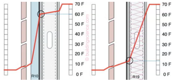
Cross-Sections Illustrating Continuous vs. Stud Cavity Thermal Envelope – Showing Impact on Thermal Gradient & Sheathing Temperature Within Assembly (Courtesy of Building Science Corp.)
Critically, the ratio of exterior-to-interior insulation must be calibrated to the climate. In cold and very cold climates (IECC Climate Zones 5–8), a higher proportion of the total R-value must be located outboard of the sheathing or air barrier to maintain sheathing temperatures above the dew point during winter. In warm and mixed climates (Zones 1–4), the risk direction reverses seasonally — inward-driven moisture during cooling periods must be evaluated with equal care.
Hygrothermal analysis tools such as WUFI® allow enclosure consultants and design teams to model the temperature gradient and moisture conditions at each layer of a proposed assembly across seasonal conditions — confirming whether the insulation strategy achieves dew-point control before construction begins.
Common High-Performance Insulation Types
A wide range of insulation products are available to the design and construction community. The following summarizes the most commonly specified high-performance insulation types, along with their key performance characteristics, advantages, and limitations.
Closed-Cell Spray Polyurethane Foam (ccSPF)
ccSPF is a two-component, spray-applied rigid foam insulation that expands in place to fill cavities and irregular surfaces. It typically achieves R-values of R-6.0 to R-7.0 per inch and acts simultaneously as an air barrier, vapor retarder, and insulation layer.
- Advantages: Very high R-value per inch; air- and vapor-impermeable; adheres to most substrates; can provide structural rigidity; eliminates need for separate air barrier at framing.
- Limitations: Relatively high cost; requires professional installation; vapor-impermeability can limit drying potential of assemblies at thicker applications; environmental concerns related to blowing agents; difficult to inspect post-installation; off-gassing during and after application requires precautions.
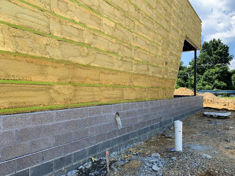
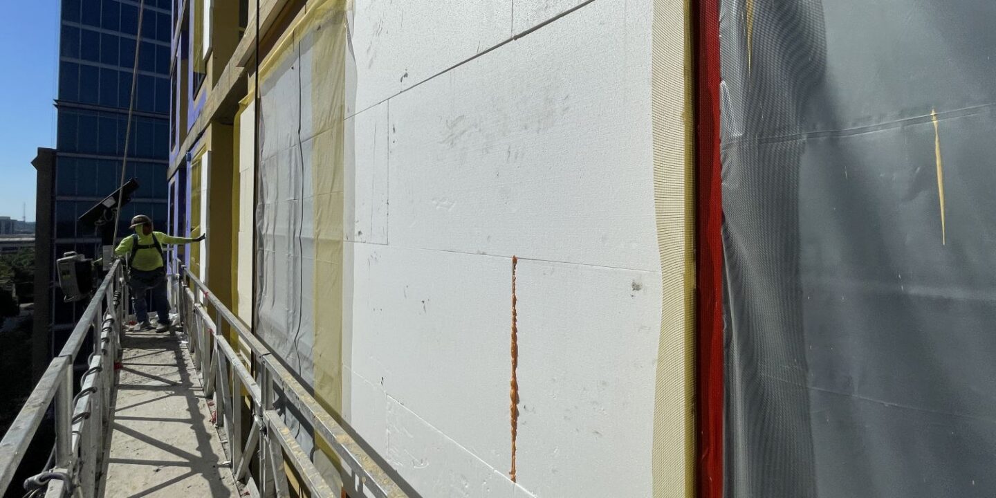
Application of Closed-Cell SPF as Continuous Exterior Insulation for Ice Rink Facility
Open-Cell Spray Polyurethane Foam (ocSPF)
ocSPF is a lower-density spray foam with a softer, open cell structure. It typically achieves R-values of R-3.5 to R-3.8 per inch and functions as an air barrier but is vapor-permeable.
- Advantages: Excellent air sealing; vapor-open (allows drying); lower cost than ccSPF; good for irregular cavities and difficult-to-reach areas; sound attenuation.
- Limitations: Lower R-value per inch than ccSPF; not suitable as a standalone vapor retarder; requires vapor management strategy in cold climates; can absorb and hold moisture if in contact with liquid water; not suitable for below-grade or wet applications.
Extruded Polystyrene (XPS)
XPS is a rigid foam board insulation manufactured through an extrusion process, typically blue, pink, or green depending on manufacturer. It achieves R-5.0 per inch and has low vapor permeability (Class II vapor retarder at standard thicknesses).
- Advantages: Consistent R-value; moisture-resistant (suitable for below-grade, IRMA roof assemblies, and plaza deck applications); good compressive strength; widely available.
- Limitations: R-value degrades slightly over time as blowing agents dissipate; high global warming potential (GWP) due to blowing agents; vapor semi-impermeability must be accounted for in assembly design; not suitable in fire-exposed applications without ignition barrier.
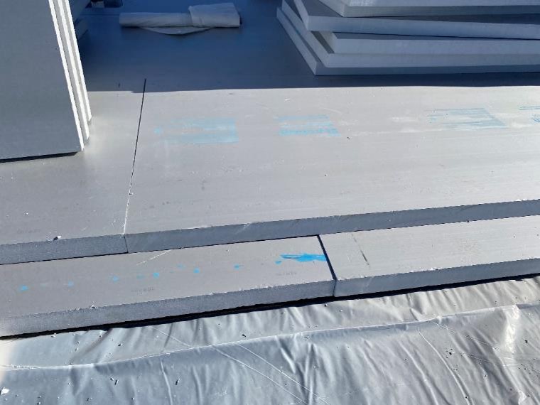
Typical Configuration of XPS Insulation Used for Inverted Roof Membrane Assembly (IRMA)
Expanded Polystyrene (EPS)
EPS is a rigid foam board manufactured by expanding polystyrene beads. It typically achieves R-3.6 to R-4.2 per inch and has higher vapor permeability than XPS.
- Advantages: Lower GWP than XPS; stable long-term R-value; vapor-open compared to XPS (can allow drying); good compressive strength at higher densities; cost-effective.
- Limitations: Lower R-value per inch than XPS or ccSPF; can absorb moisture if not properly protected; requires ignition barrier in exposed applications; less moisture-resistant than XPS for direct burial.
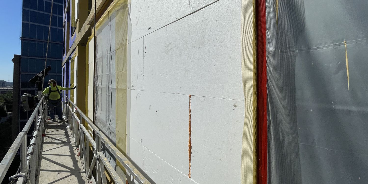
Typical Application of EPS Insulation – Used as Part of EIFS Façade Assembly
Polyisocyanurate (Polyiso)
Polyiso is a rigid foam board with a foil or glass-fiber facer, achieving nominal R-values of R-6.0 to R-6.5 per inch. It is among the most commonly specified continuous insulation products for low-slope roofing systems and commercial wall assemblies.
- Advantages: Highest R-value per inch among rigid board products; foil facers provide additional air and vapor control; widely used in roofing assemblies; relatively lower environmental impact than XPS.
- Limitations: R-value is temperature-dependent and degrades significantly in cold temperatures — a critical consideration in cold climate roofing design; moisture absorption can reduce performance over time; requires ignition barrier; facers can delaminate if exposed to prolonged moisture.

Typical Application of Polyiso Insulation – Used as Part of Conventional, Built-up Roof Assembly
Mineral Wool (Stone Wool / Slag Wool)
Mineral wool insulation — available as batt or rigid board — is manufactured from volcanic rock or industrial slag. It achieves R-3.7 to R-4.3 per inch in batt form and R-4.0 to R-4.6 per inch as rigid board.
- Advantages: Non-combustible (fire-resistant); inherently vapor-open and hydrophobic (repels liquid water while allowing drying); dimensionally stable; good acoustic performance; suitable for use in continuous insulation applications.
- Limitations: Lower R-value per inch than foam products; heavier than foam boards; more expensive than fiberglass batt; requires careful detailing at joints for continuous insulation applications.
Fiberglass Batt
Traditional fiberglass batt insulation remains widely used in cavity applications. It typically achieves R-3.1 to R-4.3 per inch depending on density and product type.
- Advantages: Low cost; widely available; vapor-open; easy to install; no blowing agents or off-gassing concerns.
- Limitations: Performance highly sensitive to installation quality — gaps, compression, and voids significantly reduce effective R-value; subject to convective looping at low densities; not suitable as a continuous insulation layer; provides no air barrier function.
Code Prescriptive Insulation Requirements
The 2021 International Energy Conservation Code (IECC) and its commercial counterpart, ASHRAE 90.1-2019, establish minimum prescriptive insulation requirements organized by climate zone. These requirements are assembly-specific and differentiate between continuous insulation (ci) and cavity insulation, reflecting the building science principle that the location of insulation within an assembly is as important as its total R-value.
The following summarizes prescriptive insulation requirements for key assembly types across common climate zones. Note that adopted codes vary by jurisdiction — DC Metro jurisdictions and the State of Georgia have adopted different code cycles and amendments. Compliance with the locally adopted code should always be confirmed.
Exterior Walls (Above-Grade)
For mass walls, metal framing, and wood-framed assemblies, the IECC prescribes minimum total R-values as well as minimum continuous insulation (ci) values outboard of the framing. The ci requirement exists specifically to address the thermal bridging penalty of framing members and to ensure that sheathing temperatures remain above the dew point in cold climates.
- Climate Zones 1–2 (e.g., Miami, Houston): Total R-13 cavity insulation minimum for wood-framed walls; metal-framed walls require R-13 cavity + R-3.8 ci minimum.
- Climate Zone 3 (e.g., Atlanta): R-20 cavity, or R-13 cavity + R-5 ci for wood-framed walls; metal-framed walls require R-13 + R-7.5 ci.
- Climate Zone 4 (Marine) & Zone 5 (e.g., Washington D.C., Chicago): R-20 cavity + R-5 ci or R-13 cavity + R-10 ci for wood-framed walls; metal-framed walls require R-13 + R-15.6 ci.
- Climate Zones 6–8 (e.g., Minneapolis): R-20 cavity + R-10 ci or R-13 + R-15 ci for wood-framed walls; increasingly stringent ci requirements for metal-framed assemblies.
For mass walls (concrete, masonry), ci requirements are generally lower at warmer climate zones but increase substantially in Zones 5–8, where the thermal mass benefit diminishes relative to the heating load.
Below-Grade Walls
Below-grade wall assemblies are subject to both thermal and moisture management requirements. Insulation in below-grade applications must be moisture-resistant (typically XPS or EPS with drainage board protection) and is typically applied to the exterior face of the foundation wall to keep the wall mass thermally conditioned and to protect waterproofing membranes from thermal cycling and backfill damage.
- Climate Zones 1–2: No minimum continuous insulation required below grade per IECC; however, ASHRAE 90.1 may impose requirements for conditioned below-grade spaces.
- Climate Zones 3–4: R-7.5 ci minimum at below-grade walls.
- Climate Zones 5–8: R-10 to R-15 ci minimum, depending on zone and assembly type.
From a durability standpoint, exterior-applied insulation at below-grade walls also provides critical protection to waterproofing membranes, reducing thermal stress and mechanical damage from backfill. Coordination between the structural, waterproofing, and insulation systems is essential at this interface.
On-Grade Slabs
Slab-on-grade insulation is among the most commonly omitted — or minimally detailed — elements of the thermal envelope. Cold slab edges and perimeter conditions are significant sources of heat loss and represent a persistent source of thermal bridging and condensation risk in slab-on-grade construction. Code requirements address slab edge insulation specifically:
- Climate Zones 1–2: No minimum slab insulation required per IECC.
- Climate Zone 3 (e.g., Atlanta): R-7.5 for at least 24 inches below grade at heated slab perimeters.
- Climate Zones 4–5 (e.g., Washington D.C.): R-10 for at least 24 inches below grade.
- Climate Zones 6–8: R-10 to R-15 for 48 inches below grade or full slab depth.
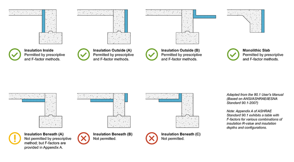
Depiction of Acceptable and Unacceptable Slab-on-Grade Insulation Applications per ASHRAE Standard 90.1
The slab edge condition at grade transitions is particularly important where the slab connects to exterior walls. Without adequate slab-edge insulation and a thoughtful thermal break detail, the slab can act as a fin radiator, conducting heat outward and creating a cold surface at the interior slab surface near the perimeter — a common location for condensation and mold growth in high-humidity occupancies.
Roofs
Roof assemblies typically require the highest insulation R-values in the building envelope, reflecting the dominant role of the roof in overall building heat loss and gain. The IECC prescribes minimum continuous insulation for low-slope (nonresidential) roofs as follows:
- Climate Zones 1–2: R-20 ci minimum for low-slope roofs.
- Climate Zones 3–4 (e.g., Atlanta, Washington D.C.): R-25 ci minimum.
- Climate Zones 5–6: R-30 ci minimum.
- Climate Zones 7–8: R-35 ci minimum.
For steep-slope roofs (residential), cavity insulation between rafters is supplemented with minimum ci requirements that increase with climate zone. As with walls, roof ci should be located above the roof deck wherever possible, keeping the deck temperature warm and reducing condensation risk at the deck surface — a critical concern that is addressed in more detail in the over-insulation discussion below.
The Relationship Between Insulation and Vapor Retarder Requirements
One of the most nuanced — and consequential — aspects of insulation design is its relationship to vapor retarder requirements. As discussed in a prior Enclosure Insights installment, vapor retarders are classified by permeance: Class I (≤0.1 perms), Class II (0.1–1.0 perms), and Class III (1.0–10 perms). Both the IECC and IBC define which vapor retarder classes are permissible based on climate zone.
What is less widely understood is that the amount and location of continuous insulation directly influences which vapor retarder class is required — or even whether a dedicated vapor retarder is needed at all. The IECC and IBC both recognize that when sufficient ci is placed outboard of the sheathing or air barrier, the sheathing is kept warm enough that the risk of condensation at that surface is substantially reduced. In such assemblies, a low-permeance vapor retarder on the interior — which could trap moisture and prevent inward drying — may actually increase rather than decrease moisture risk.
The IECC Table R702.7.1 establishes minimum outboard ci R-values by climate zone that, when achieved, permit the use of a Class III vapor retarder (a vapor-open material) on the warm side of the assembly, rather than requiring the more vapor-restrictive Class I or II retarders. For example:
- Climate Zone 4 (e.g., Washington D.C.): R-7.5 ci outboard of the sheathing permits a Class III vapor retarder inboard; without sufficient ci, a Class II retarder is required.
- Climate Zone 6: R-11.25 ci outboard permits a Class III retarder inboard.
- Climate Zone 7–8: R-15 ci outboard permits a Class III retarder.
This code framework reflects a sophisticated understanding of assembly hygrothermal behavior: insulation and vapor control are not independent design decisions. The right vapor retarder strategy depends directly on how much insulation is present and where it is located within the assembly.
The practical implication for design professionals is that specifying continuous insulation without reviewing the corresponding vapor retarder requirements — or vice versa — can result in assemblies that either do not comply with code or that inadvertently trap moisture. Enclosure consultants play a critical role in ensuring these two systems are coordinated.
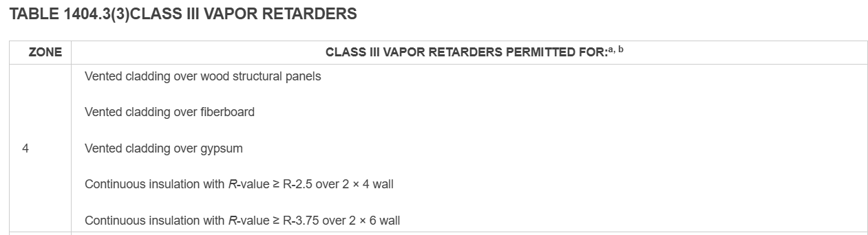
IBC Table 1404.3 – Vapor Retarder Class III Requirements for Zone 4 Based on Outboard Insulation Level
The Risks of Over-Insulating Enclosure Assemblies
More insulation is not always better. While increasing R-value generally improves energy performance, excessive insulation — or insulation placed in the wrong location within an assembly — can create serious and often concealed durability risks. This is one of the most counterintuitive principles in building science, and one that is frequently overlooked in the pursuit of high energy performance metrics.
Shifting the Dew Point onto Vulnerable Substrates
When cavity insulation is added without corresponding outboard continuous insulation, the temperature gradient within the assembly shifts inward. In cold climates, this can place the dew point within or at the exterior sheathing layer — a surface that in wood-framed construction is particularly vulnerable to moisture accumulation, mold growth, and structural degradation.
This is precisely the failure mode observed in many multi-family residential projects where dense-pack cellulose or high-density fiberglass batts are added to existing cavities without evaluating the corresponding impact on sheathing temperature. The result is a well-insulated wall that accumulates moisture at its most vulnerable layer.
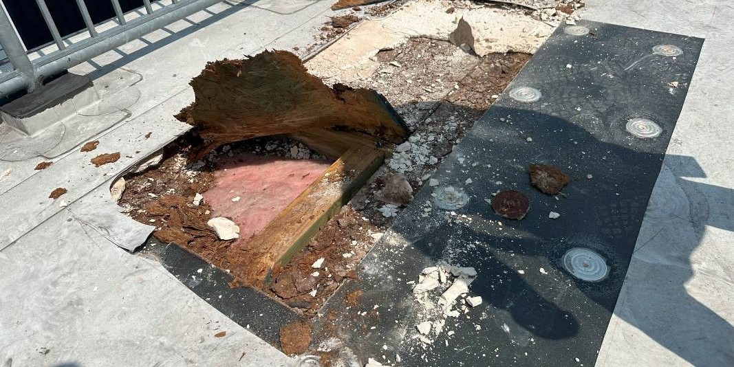
View of Extensive Plywood Roof Sheathing Damage Due to Excessive Cavity Insulation & Condensation at Interior Surfaces
Restricting Drying Potential in Roof Assemblies
Low-slope roof assemblies are particularly susceptible to over-insulation risks. When ccSPF is applied in excessive thicknesses at or below the roof deck — or when multiple layers of rigid board insulation are installed above the deck without adequate evaluation of the drying potential — any moisture that enters the assembly has no pathway for escape.
This is a well-documented failure mode in retrofit roofing applications where new insulation is added over an existing roof assembly. If the existing roof membrane or deck contains residual moisture, adding impermeable insulation above traps that moisture permanently. Field investigations by SK&A have identified significant concealed deck deterioration resulting from precisely this condition.
Trapping Moisture Between Vapor-Impermeable Layers
When vapor-impermeable insulation products (ccSPF, XPS, or foil-faced polyiso) are placed on both sides of an assembly — creating a vapor “sandwich” — any moisture that enters the assembly through construction defects, condensation, or minor leakage has no drying pathway. Progressive moisture accumulation is the predictable result, and it typically remains concealed until significant damage has occurred.
This condition arises in mixed-insulation systems where, for example, ccSPF is spray-applied to the interior face of a wall cavity while foil-faced polyiso is installed outboard as continuous insulation. Without careful hygrothermal evaluation, the assembly may appear high-performance on paper while being fundamentally incapable of drying in either direction.
Polyiso R-Value Depression in Cold Climates
Polyisocyanurate insulation exhibits a well-documented phenomenon known as R-value depression at low temperatures. While polyiso is rated at approximately R-6.0 to R-6.5 per inch at standard test temperatures (75°F mean), its effective R-value can drop to R-4.0 to R-4.5 per inch at mean temperatures below 40°F — conditions that are routinely encountered in low-slope roofing assemblies in cold and mixed climates.
A roof assembly designed to achieve R-30 using five inches of polyiso may deliver only R-20 to R-22 in practice during winter conditions — the season when thermal performance matters most. Design teams and enclosure consultants specifying polyiso in cold climate roof assemblies should apply appropriate aged-value and temperature-corrected R-value adjustments during design, or consider supplementing with EPS or mineral wool layers that maintain performance at low temperatures.
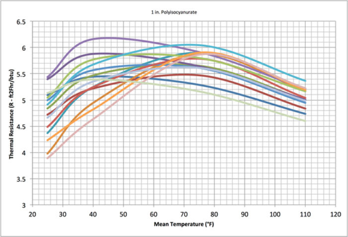
Graph Illustrating Polyiso R-Value as a Function of Mean Temperature – Showing Depression Below Rated Value in Cold Conditions
Connecting the Dots
Thermal control is not a single-product specification — it is a system-level decision that intersects with every other enclosure control layer. The insulation strategy must be evaluated in the context of:
- Where insulation is located within the assembly relative to the air and vapor control layers
- How much continuous insulation is present relative to cavity insulation, and what that ratio means for dew-point location and vapor retarder requirements
- How vapor-permeable the insulation products are, and whether the assembly retains meaningful drying potential in at least one direction
- How the insulation R-value behaves under actual temperature and humidity conditions, not just at rated test conditions
- How the insulation transitions across assembly types — at roofs, foundations, slab edges, and fenestrations — to maintain a continuous thermal envelope
An assembly with insufficient insulation loses energy.
An assembly with too much insulation — in the wrong location — can accumulate moisture invisibly until failure.
A high-performance enclosure gets both right.
What’s Next in Enclosure Insights
In the next installment of Enclosure Insights, we will turn to thermal bridging — examining the most common bridge locations in commercial and multi-family construction (slab edges, balconies, shelf angles, mullions, and parapets), how they reduce effective R-value, and what strategies are available to eliminate or mitigate them.
SK&A’s Building Enclosure Consulting + Waterproofing team brings decades of experience and specialized technical expertise to aid in the design and construction of new buildings, as well as the evaluation and maintenance of existing buildings. Learn more.