Authored by SK&A Principal Justin Long, PE, RBEC, BECxP. Follow Justin on Linked In.
Dynamic Hygrothermal Storage: How Buildings Absorb, Buffer, and Release Heat and Moisture
Throughout this year’s Enclosure Insights series, we have examined the building enclosure as a system of control layers – each one managing a specific transfer mechanism: bulk water, air, vapor, heat conduction, solar radiation, and the strategies used to intercept each before it drives energy loss, condensation, or occupant discomfort. The model underlying each of these discussions has been largely static: a steady-state boundary between a conditioned interior and an unconditioned exterior, with materials doing their work as barriers and resistors.
Reality is more dynamic. Building materials do not simply resist the flow of heat and moisture – they absorb, store, and release both in response to continuously changing conditions. The concrete slab that feels cold underfoot on a winter morning has been slowly releasing heat absorbed during the previous afternoon. The brick veneer that appears wet through a light rain event is buffering moisture that a less absorbent cladding would shed immediately as runoff – and then releasing it gradually as conditions allow. These dynamic behaviors are not incidental properties of building materials; they are performance mechanisms that can be harnessed deliberately in enclosure design to reduce peak loads, moderate interior temperature and humidity swings, and improve the long-term durability of assemblies.
This month’s Enclosure Insights examines dynamic hygrothermal storage – the coupled thermal and moisture buffering behavior of building enclosure materials – and how it is understood, quantified, and accounted for in high-performance enclosure design and energy modeling.
Two Phenomena, One System
The term hygrothermal reflects the inseparability of heat and moisture transfer in building assemblies. Temperature drives moisture movement (warmer air holds more moisture; temperature gradients drive vapor diffusion). Moisture content in turn affects the thermal properties of materials – wet insulation conducts heat more readily than dry insulation; a saturated brick masonry wall has a higher volumetric heat capacity than a dry one. These two phenomena are coupled: you cannot model one accurately without accounting for the other, and enclosure assemblies that perform well in steady-state thermal analysis can behave very differently under real dynamic conditions when moisture is part of the picture.
Hygrothermal storage operates through two distinct but related mechanisms:
- Thermal storage (thermal mass): The capacity of a material to absorb and retain heat energy, releasing it later as conditions change. Governed by the material’s heat capacity (the energy required to raise a unit of mass by one degree) and thermal diffusivity (how quickly heat moves through the material). Dense, heavy materials – concrete, masonry, earth – have high heat capacity and low thermal diffusivity, meaning they absorb large quantities of heat slowly and release it slowly.
- Moisture buffering: The capacity of a material to absorb moisture vapor from the surrounding air during high-humidity periods and release it back to the air during low-humidity periods, moderating interior relative humidity swings. Governed by the material’s sorption isotherm (the relationship between ambient relative humidity and the moisture content the material reaches at equilibrium) and its moisture diffusivity (how quickly moisture moves within the material in response to a humidity gradient).
Both phenomena operate on a time-lag principle: the stored quantity – heat or moisture – is absorbed during a peak period and released during a trough, shifting the timing of the load relative to when it was generated. This time-lag effect is the mechanism by which hygrothermal storage reduces peak loads, even when it does not reduce total loads over a longer cycle.
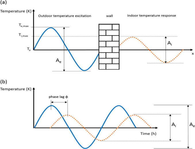
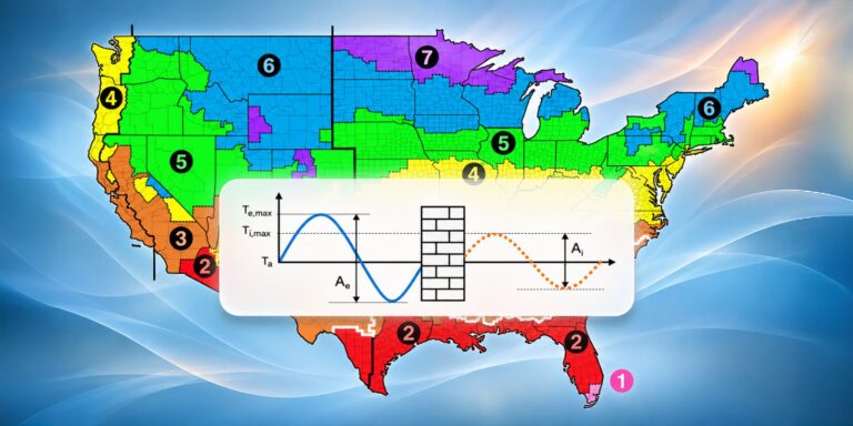
Diagram Illustrating Thermal Time-Lag for an Exterior Wall Assembly –Exterior Temperature Peak, Interior Temperature Response, and Phase Shift Between the Two
Thermal Mass: Heat Stored, Heat Shifted
The Physics
The thermal storage capacity of a material is characterized by its volumetric heat capacity – the product of its density (ρ) and specific heat capacity (cₚ), expressed in units of Btu/(ft³·°F). Dense materials with high specific heat – concrete, brick, stone masonry, water – store large quantities of thermal energy per unit volume. Lightweight materials – wood framing, insulation, gypsum board – have comparatively low volumetric heat capacity and contribute little to thermal storage.
Equally important is thermal diffusivity – the ratio of a material’s thermal conductivity to its volumetric heat capacity. A material with low thermal diffusivity absorbs heat at its surface but transmits it slowly through its thickness, creating the characteristic time-lag and decrement factor behavior of enclosure assemblies:
- Time lag: The delay between the peak temperature at the exterior surface of a wall and the peak temperature at its interior surface. For a dense brick masonry wall of sufficient thickness, this lag can exceed 8 to 12 hours, effectively shifting the peak solar or ambient heat gain from the afternoon into the evening or overnight period, when it is cheaper or less disruptive to condition.
- Decrement factor: The ratio of the interior surface temperature amplitude to the exterior surface temperature amplitude. A decrement factor of 0.2 means that only 20 percent of the exterior daily temperature swing is transmitted to the interior – the wall has attenuated the peak by 80 percent. Heavier, thicker assemblies achieve lower decrement factors and greater peak attenuation.
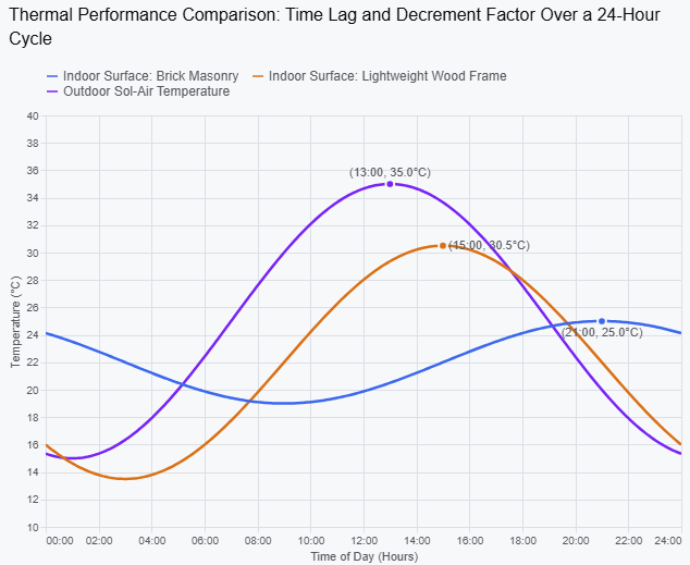
Comparative Graphs of Time Lag and Decrement Factor for Lightweight Wood Frame vs. Brick Masonry Mass Wall Assemblies Under Identical Solar and Ambient Temperature Conditions
Where Thermal Mass Is and Is Not Effective
Thermal mass is most effective as a passive load management strategy under specific climatic and occupancy conditions. It performs best in climates with large diurnal temperature swings – where the difference between daytime highs and nighttime lows is sufficient to drive meaningful charging and discharging cycles. Dry climates (ASHRAE Climate Zones 3B, 4B, 5B) and moderate continental climates with clear, sunny days and cool nights are the conditions under which thermal mass has historically delivered the largest documented performance benefits.
In hot-humid climates such as Atlanta (Climate Zone 2A/3A), where nighttime temperatures remain high throughout the summer cooling season, the discharging cycle that thermal mass depends on is compromised: the wall cannot cool overnight sufficiently to absorb the following day’s solar gain without itself contributing to interior heat gain. In these climates, thermal mass without nighttime ventilative cooling can actually worsen peak cooling loads by retaining heat and releasing it into the conditioned space during periods when it is most costly to remove. The performance benefit of thermal mass in hot-humid climates is context-dependent and should be evaluated through energy modeling rather than assumed.
In mixed climates such as the DC Metro region (Climate Zone 4A), thermal mass can provide meaningful heating-season benefits – particularly in south-facing assemblies where it can absorb passive solar gain during the day and release it into the space at night – while its summer performance depends heavily on nighttime temperatures and ventilation strategy. The DC Metro climate’s relatively moderate diurnal swings in summer limit the thermal mass benefit during the cooling season compared to drier continental climates at similar latitudes.
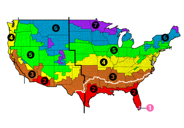
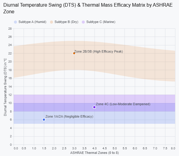
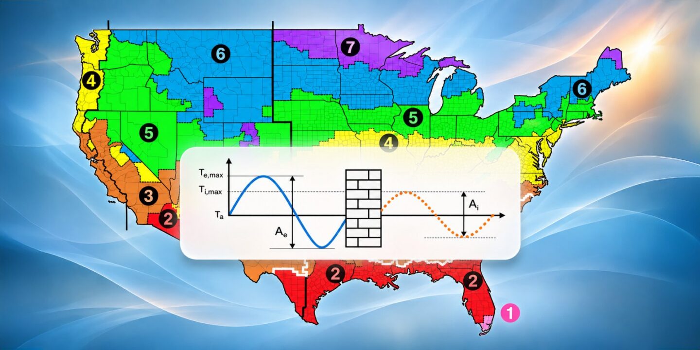
Map of ASHRAE Climate Zones with Annotation of Diurnal Temperature Swing Ranges and Relative Thermal Mass Effectiveness by Zone
Thermal Mass and Insulation: Placement Matters
The interaction between thermal mass and insulation placement is one of the most consequential and most frequently misunderstood aspects of exterior wall design. The effectiveness of thermal mass depends on its thermal connection to the conditioned space: mass that is isolated from the interior by insulation cannot exchange heat with the interior and therefore cannot moderate interior temperature swings regardless of how much heat it absorbs.
This creates a design tension that must be resolved deliberately:
- Insulation outboard of mass (mass inside ci): Placing continuous insulation on the exterior face of a brick mass masonry wall, for example, keeps the mass thermally connected to the interior, allowing it to participate fully in the buffering cycle. It also keeps the mass above the dew point throughout the year – a durability benefit. This is the configuration recommended for climates where passive heating-season thermal mass benefits are sought, and it is consistent with the continuous insulation strategy advocated throughout this series.
- Insulation inboard of mass (mass outside ci): Placing insulation on the interior face of a mass wall decouples the mass from the conditioned space, effectively eliminating its thermal storage contribution to interior comfort. The wall behaves as a well-insulated lightweight assembly from the interior’s perspective. This configuration is thermally efficient but sacrifices the dynamic buffering benefit that justified the mass in the first place.
- Insulation distributed within mass (split ci): Some assemblies – such as insulated concrete forms (ICF) or sandwich panel systems with a foam core between two concrete layers – distribute insulation within the mass, with concrete on both the interior and exterior faces. These systems provide good thermal resistance, some interior-side thermal mass benefit, and the exterior mass layer contributes to moisture buffering and durability. They are an effective compromise in climates where both insulation performance and thermal mass benefit are priorities.
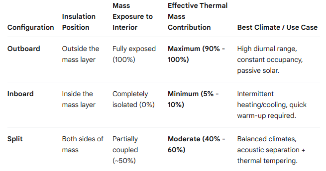
Table Comparing Insulation Placement Relative to Thermal Mass Layer – Outboard, Inboard, and Split Configurations – with Annotation of Effective Thermal Mass Contribution in Each Case
Moisture Buffering: The Humidity Flywheel
Moisture buffering is the hygroscopic analog of thermal mass – the capacity of building materials to absorb moisture vapor from the interior air during high-humidity periods and release it during low-humidity periods, acting as a passive humidity regulator. The phenomenon is well-documented in building science literature but receives comparatively little attention in commercial enclosure design practice, where mechanical systems are typically assumed to carry the full burden of interior humidity control.
In reality, the interior surfaces of a building – gypsum board, wood, concrete, masonry, textiles, and paper products – are continuously exchanging moisture vapor with the interior air. The magnitude of this exchange depends on the materials’ moisture buffer value (MBV), a property defined by the Nordic research community as the mass of water vapor absorbed or desorbed per unit of exposed surface area per unit change in relative humidity, measured over a standardized 8-hour adsorption / 16-hour desorption cycle (i.e., the Nordtest protocol). Materials with high MBV – clay plasters, wood, hygroscopic concrete products, cellulose-based materials – can absorb and release substantial quantities of moisture vapor in response to diurnal humidity swings.
Practical Consequences for Interior Humidity
The practical consequence of moisture buffering is the damping of interior relative humidity fluctuations. In a space with highly hygroscopic interior surfaces, a pulse of moisture generation – from cooking, showering, occupancy, or transient outdoor air infiltration – produces a smaller, slower rise in interior RH than the same pulse in a space with impermeable interior finishes (painted drywall, ceramic tile, vinyl wallcovering). The hygroscopic surfaces absorb the moisture pulse and release it gradually over the following hours as interior humidity subsides, moderating the peak without requiring additional mechanical dehumidification.
This behavior has implications for mechanical system sizing and enclosure moisture management alike. Buildings with high-MBV interior surfaces may require less peak dehumidification capacity than the same building with impermeable finishes – a factor that can reduce mechanical system first cost and operating energy. From an enclosure durability standpoint, moisture buffering at the interior surface layer can reduce the magnitude of inward-driven moisture loads on the enclosure assembly during periods of high interior humidity, complementing the vapor management strategy discussed in earlier installments of this series.
Moisture Buffering and Enclosure Durability
Moisture buffering also operates at the enclosure assembly scale. Hygroscopic materials within a wall or roof assembly – wood sheathing, cellulose insulation, wood fiber board, unfaced mineral wool – absorb moisture during periods of elevated humidity within the assembly (from air/vapor drive, condensation events, or construction moisture) and release it during drying periods. This buffering behavior extends the drying tolerance of an assembly – its capacity to absorb and manage transient moisture events without accumulating moisture to damaging levels.
Hygrothermal analysis tools such as WUFI® – the industry-standard transient hygrothermal simulation platform developed by Fraunhofer IBP – model this dynamic behavior explicitly, simulating the coupled heat and moisture transport through multi-layer assemblies under real climate conditions over multi-year simulation periods. WUFI analysis accounts for:
- Vapor diffusion and liquid moisture transport within each material layer
- Sorption and desorption behavior (the moisture buffering cycle) within hygroscopic materials
- Capillary redistribution of liquid water within porous materials
- The effect of moisture content on thermal conductivity (wet materials conduct heat more readily)
- Climate-driven wetting and drying cycles over multiple years, revealing accumulation trends that single-season analysis misses
The distinction between a hygroscopic assembly – one that can absorb and release moisture dynamically – and a vapor-sealed assembly – one with impermeable layers on one or both sides that prevent moisture exchange – has direct consequences for WUFI analysis outcomes. Assemblies that rely on drying as their primary moisture management strategy (open-drain, back-ventilated, or hygroscopic-material systems) perform well in WUFI when the drying pathway is clear and the moisture buffering capacity of the materials is sufficient to manage transient wetting events. Assemblies that depend on vapor sealing on both sides can accumulate moisture from construction, minor condensation events, or incidental infiltration with no drying pathway available – a condition that WUFI identifies reliably but that point-in-time steady-state analysis does not.
Materials in Practice: Hygrothermal Storage Capacity by Assembly Type
The following summarizes the hygrothermal storage characteristics of the most common commercial and multi-family enclosure assembly types, with attention to how their dynamic properties interact with the control layer strategies discussed throughout this series.
Concrete and Masonry Assemblies
Concrete and masonry offer the highest volumetric heat capacity of any common enclosure material, with concrete ranging from approximately 460 to 500 Btu/(ft³·°F) and brick from 230 to 270 Btu/(ft³·°F). Both materials are moderately hygroscopic and contribute meaningfully to moisture buffering when their surfaces are exposed to interior air or when they are used in contact with hygroscopic insulation layers. The moisture buffering contribution of concrete and masonry is reduced substantially by impermeable interior finishes – epoxy coatings, vapor-sealed paint, or non-breathable cladding over exterior faces.
The primary enclosure design consideration for concrete and masonry assemblies is insulation placement, as discussed above. Exterior continuous insulation preserves the interior-side thermal mass benefit and protects the mass from freeze-thaw cycling and carbonation-driven deterioration – a durability benefit that compounds the thermal performance advantage.
Light-Frame Wood and Metal Stud Assemblies
Light-frame assemblies – the dominant construction type in mid-rise multi-family construction – have low volumetric heat capacity and limited thermal mass contribution. The primary hygrothermal storage element in a light-frame assembly is the wood sheathing, which is moderately hygroscopic and contributes meaningfully to moisture buffering at the assembly level. OSB and plywood sheathings have sorption isotherms that allow them to absorb and release moisture in response to changing conditions within the assembly, providing a buffer against transient condensation events that might otherwise produce liquid water accumulation at the sheathing surface.
This is precisely why sheathing moisture content is the primary failure criterion tracked in WUFI analysis of light-frame assemblies: if the dynamic simulation shows the sheathing moisture content consistently exceeding 18 to 20 percent by weight (the threshold for mold growth) or approaching fiber saturation point (the threshold for decay), the assembly’s hygrothermal storage capacity is insufficient to buffer the moisture loads it is experiencing, and the assembly design must be revised. The interplay between the sheathing’s buffering capacity, the assembly’s vapor management strategy, and the insulation placement is the central variable in the WUFI analysis of these assemblies.
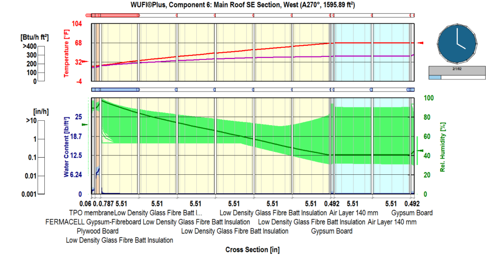
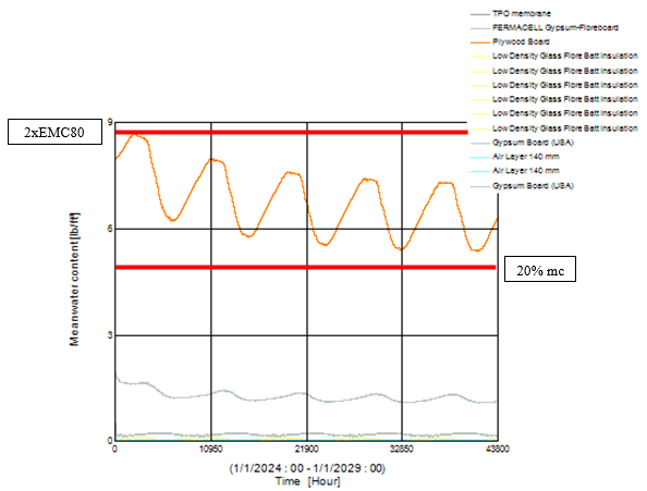
WUFI® Simulation Showing Wood Sheathing Moisture Content Over a 5-Year Simulation Period – Roof Assembly with Inadequate Outboard Continuous Insulation in Climate Zone 4A
Hygroscopic Insulation Materials
As discussed in the July installment on high-performance insulation, the hygroscopic character of an insulation material directly influences the drying potential of the assembly it occupies. Cellulose, wood fiber board, and unfaced mineral wool are hygroscopic materials with meaningful moisture buffer values; they can absorb transient moisture and release it during drying periods, contributing to assembly resilience. Closed-cell SPF, XPS, and foil-faced polyiso are essentially non-hygroscopic and contribute nothing to moisture buffering; when placed in assemblies without adequate drying pathways, they convert what would otherwise be a reversible moisture buffering event into a persistent accumulation condition.
The selection of insulation materials therefore carries hygrothermal storage implications beyond the R-value and vapor permeance considerations discussed in July. An assembly that substitutes ccSPF for cellulose in a retrofit application – without evaluating the change in moisture buffering capacity and drying potential – may produce a system that performs well in steady-state thermal analysis but accumulates moisture under transient conditions that the original assembly would have buffered and dried.
Modeling Hygrothermal Storage: From WUFI to Energy Simulation
The dynamic hygrothermal behavior described in this installment is not captured by steady-state methods – neither the isothermal planes method for effective R-value nor the steady-state vapor diffusion analysis that underlies simplified dew-point checks. Capturing it requires transient simulation tools that model the time-dependent coupled heat and moisture behavior of assemblies and buildings under real climate conditions.
Two categories of tool are relevant to enclosure design practice:
- Assembly-scale hygrothermal simulation (WUFI®, DELPHIN): These tools model coupled heat and moisture transport through multi-layer enclosure assemblies under transient climate conditions. They are the appropriate tools for evaluating assembly durability, drying potential, condensation risk over multi-year cycles, and the moisture buffering capacity of specific material combinations. WUFI Pro (for wall and roof cross-sections) and WUFI 2D (for two-dimensional junctions and thermal bridges) are the industry-standard platforms in North American enclosure consulting practice.
- Building energy simulation (EnergyPlus, eQUEST, IES-VE): Whole-building energy simulation tools model the thermal mass contribution of enclosure assemblies to building energy performance through dynamic thermal zone calculations. EnergyPlus, the engine underlying OpenStudio and several commercial platforms, uses the Conduction Transfer Function (CTF) method to model transient heat storage in enclosure assemblies, capturing the time-lag and decrement factor effects on cooling and heating loads. These tools are the appropriate platform for quantifying the energy performance benefit of thermal mass strategies at the whole-building level and for credit under ASHRAE 90.1 energy modeling compliance paths.
The gap between these two tool categories – assembly-scale hygrothermal analysis and building-scale energy simulation – is a known limitation of current practice. WUFI models the moisture behavior of assemblies with high fidelity but does not feed directly into energy compliance modeling. EnergyPlus models building energy performance dynamically but uses simplified hygrothermal assumptions for enclosure assemblies. For high-performance projects where both moisture durability and energy performance are design targets, both tools should be deployed in coordination – with enclosure consultants responsible for the WUFI analysis and the energy modeler responsible for the EnergyPlus simulation, working from a shared assembly definition.
Why This Matters
Dynamic hygrothermal storage is not a concept that changes what enclosure consultants specify in most projects. Concrete is still concrete; gypsum board is still gypsum board. What changes is the understanding of how those materials behave under real conditions – and therefore how assemblies should be designed, analyzed, and commissioned to take advantage of their dynamic properties or to avoid being undermined by them.
The enclosure consultant who understands hygrothermal storage recognizes that:
- A CMU backup wall with outboard continuous insulation is not just an R-value calculation – it is a thermal mass asset whose contribution to interior comfort and energy performance depends on its thermal connection to the conditioned space.
- A wood-sheathed light-frame assembly is not just an air barrier substrate – it is a hygroscopic buffer whose moisture content at any given time under transient climate conditions determines whether the assembly dries safely or accumulates toward failure.
- A retrofit that replaces hygroscopic cavity insulation with closed-cell spray foam is not just an R-value upgrade – it may be eliminating the assembly’s primary moisture buffering mechanism without providing an alternative drying pathway.
- An energy model that captures the thermal mass benefit of a heavyweight assembly is not overestimating performance – it is accounting for a real dynamic behavior that a steady-state calculation would miss.
Enclosure materials are not static barriers.
They absorb heat and moisture when conditions drive loading, and release both when conditions allow drying and cooling.
Understanding that dynamic behavior is what separates an assembly that endures from one that accumulates — slowly, invisibly, until it fails.
What’s Next in Enclosure Insights
In the final installment of this year’s Enclosure Insights series, we close with HVAC dynamics and the point where the mechanical system and the building enclosure meet as a single dynamic system. We will examine how mechanical pressurization and depressurization drive infiltration and exfiltration through the air control layer, how those pressure relationships move moisture into or out of assemblies, and how the mechanical drying potential of a conditioned space can either help or hinder an assembly’s ability to dry. The enclosure and the HVAC system are often designed and commissioned separately, but their performance is interdependent. Understanding that relationship is the last piece of dynamic performance control, and it sets up the case for integrated verification across the whole enclosure.
SK&A’s Building Enclosure Consulting + Waterproofing team brings decades of experience and specialized technical expertise to aid in the design and construction of new buildings, as well as the evaluation and maintenance of existing buildings. Learn more.