Authored by SK&A Principal Justin Long, PE, RBEC, BECxP. Follow Justin on Linked In.
Shading & Daylighting Design: Controlling Solar Loads Before They Reach the Glass
Last month’s Enclosure Insights examined the glazing unit itself – how low-emissivity coatings, spectrally selective transmission, multi-pane configurations, and warm-edge spacers work together to manage the three modes of heat transfer across the fenestration assembly. We closed with a fundamental observation: even the highest-performing glazing available today delivers a fraction of the thermal resistance of a code-minimum opaque wall, and for buildings with significant glazed area, fenestration performance is often the single largest variable in enclosure energy, comfort, and condensation outcomes.
This month, we turn from the glazing unit to the strategies used to control what reaches it. Passive shading design – the use of building-integrated horizontal overhangs, vertical fins, combined louver systems, and orientation-based strategies – is among the oldest tools in the architectural repertoire. It is also among the most underutilized in contemporary commercial and multi-family practice, where glazing schedules are frequently relied upon to carry the entire solar load management burden. Understanding how shading geometry works, where it works, and where it does not is essential to building enclosures that perform as designed across the full annual cycle of solar conditions.
The Solar Load Problem
Solar radiation arrives at a building façade as a function of three variables: the altitude of the sun above the horizon, the azimuth of the sun relative to the façade orientation, and the intensity of the direct and diffuse radiation reaching the site. These variables change continuously throughout the day and across the year, tracing a predictable path governed by latitude, season, and time. The practical consequence for enclosure design is that solar loading on any given façade is not a single number – it is a dynamic, orientation-dependent profile that varies from hour to hour and month to month.
The performance metric that captures the solar load contribution of a glazing assembly – the Solar Heat Gain Coefficient (SHGC) – is a whole-sky, hemispherical rating measured at normal incidence under standard conditions. It tells you how much of the incident solar energy enters the building through the glass, but it does not account for how much solar energy actually strikes the glass at any given moment. That quantity – the incident solar radiation – is what shading design controls. A well-designed shading system reduces incident radiation to near zero during peak cooling periods, allowing even a moderate-SHGC glazing to deliver low solar heat gain in practice. A poorly conceived shading system, or none at all, leaves the glazing SHGC as the only line of defense against whatever the sun delivers.
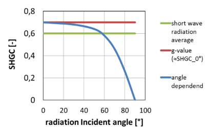
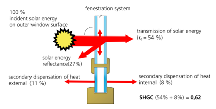
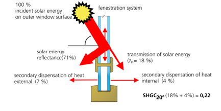
Graph of Solar Heat Gain Coefficient (SHGC) as a Function of Incident Angle of Radiation and Graphical Sections of Direct and Incident Solar Radiation
The distinction matters because shading and glazing selection are not interchangeable tools – they address different portions of the solar load management problem, and the most effective enclosure designs use both deliberately.
Radiation-control glazing manages the diffuse sky radiation and the solar energy that penetrates any gaps in the shading strategy; passive shading elements eliminate direct beam radiation during the periods when it is most intense and most costly to condition.
Orientation as the Governing Variable
Before examining individual shading devices, it is worth establishing the single principle that governs all passive shading design: façade orientation determines the solar geometry, and solar geometry determines which shading strategies are effective. This is not a nuance – it is a fundamental constraint.
A shading device optimized for one orientation can be nearly useless on another, and applying the same shading strategy uniformly across all exposures of a building is a reliable path to underperforming façades on some elevations and overglazed, unshaded ones on others.
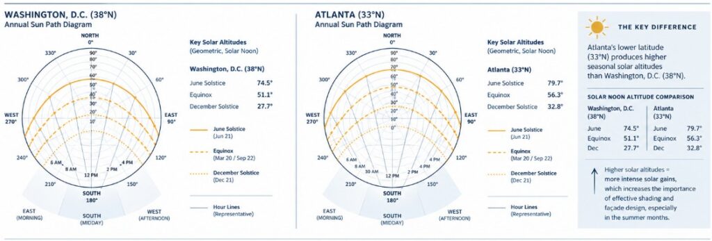
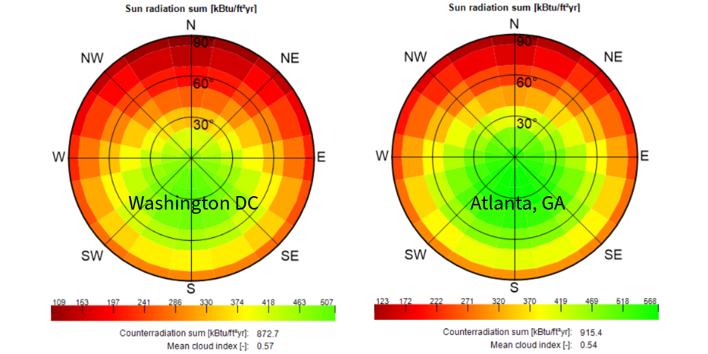
Sun Path Diagram and Sun Radiation Charts for Washington DC (Left) and Atlanta, GA (Right) Illustrating the Increase in Solar Radiation Intensity
South-Facing Façades
In the northern hemisphere, south-facing façades receive direct solar radiation when the sun is at its highest altitude – near solar noon, when the sun’s path is most nearly overhead. This geometry is the most favorable for fixed horizontal shading. A properly sized horizontal overhang can block the high-altitude summer sun – when solar heat gain is most costly – while admitting the lower-altitude winter sun – when passive solar heat gain contributes to heating load reduction. For DC Metro latitudes (approximately 38°N), the summer solstice sun at noon reaches an altitude of approximately 75°; the winter solstice noon sun drops to approximately 29°. A horizontal overhang sized to shade the window fully at 75° altitude will admit full winter sun at 29° – a clean seasonal cutoff that is achievable with fixed geometry on south-facing façades.
At Atlanta latitudes (approximately 33°N), the summer noon altitude reaches approximately 80° and the winter noon altitude drops to approximately 34°. The solar altitude range is similar, and the same horizontal shading logic applies — though the shading season extends longer into spring and fall due to Atlanta’s warmer climate and longer cooling season. For projects in Climate Zone 3A, south-facing façades with proper horizontal overhangs are among the most reliably effective passive solar control conditions in the building’s enclosure.
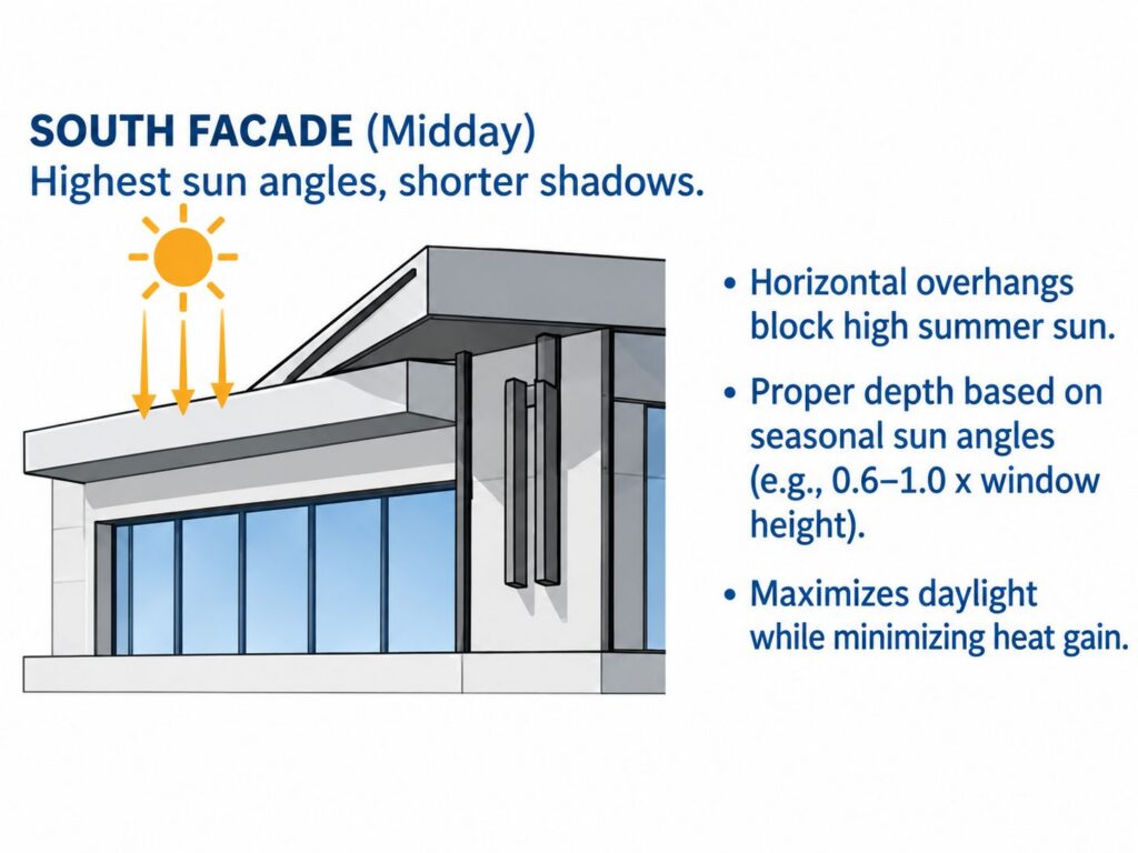
Illustration of Horizontal Overhang Shading for South Elevation Facades
East- and West-Facing Façades
East- and west-facing façades present a fundamentally different and more challenging solar geometry. These exposures receive direct sun during the morning and afternoon, respectively, when the sun is at low altitude and high azimuth – arriving nearly horizontally from the side rather than steeply from above. A horizontal overhang, which shades effectively against high-altitude sun, provides almost no protection against low-angle sun arriving at or near the horizon. The classic failure mode: a building with substantial horizontal overhangs on all four elevations that is effectively shaded on its south façade and essentially unshaded on its east and west façades during peak morning and afternoon solar hours.
East and west exposures are responsible for a disproportionate share of solar heat gain in commercial and multi-family buildings, and they are the exposures where glazing SHGC carries the most weight in the absence of effective shading. For buildings with significant east or west glazed area, vertical fins, egg-crate combined systems, or dynamic shading strategies are required to meaningfully intercept low-angle beam radiation. Fixed horizontal elements alone are insufficient.
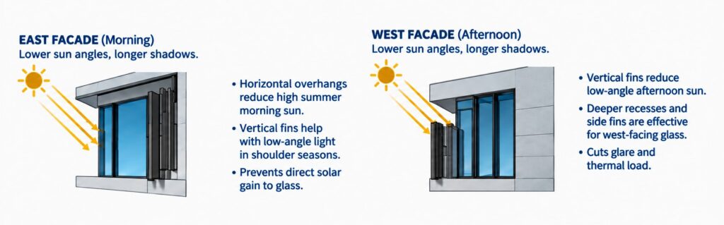
Illustration of Horizontal Overhangs and Vertical Fin Shading for East & West Elevation Facades
North-Facing Façades
North-facing façades receive no direct beam radiation during most of the year in northern hemisphere locations, making them the preferred exposure for maximizing glazed area with minimal solar heat gain risk. The solar load on north façades is dominated by diffuse sky radiation rather than direct beam radiation, and diffuse radiation is managed by glazing SHGC rather than by geometric shading. Shading devices on north-facing façades provide little solar load benefit and can reduce daylight quality without a corresponding energy return. The enclosure design priority on north-facing glazing is typically thermal performance (U-factor and condensation resistance) and view quality rather than solar control.
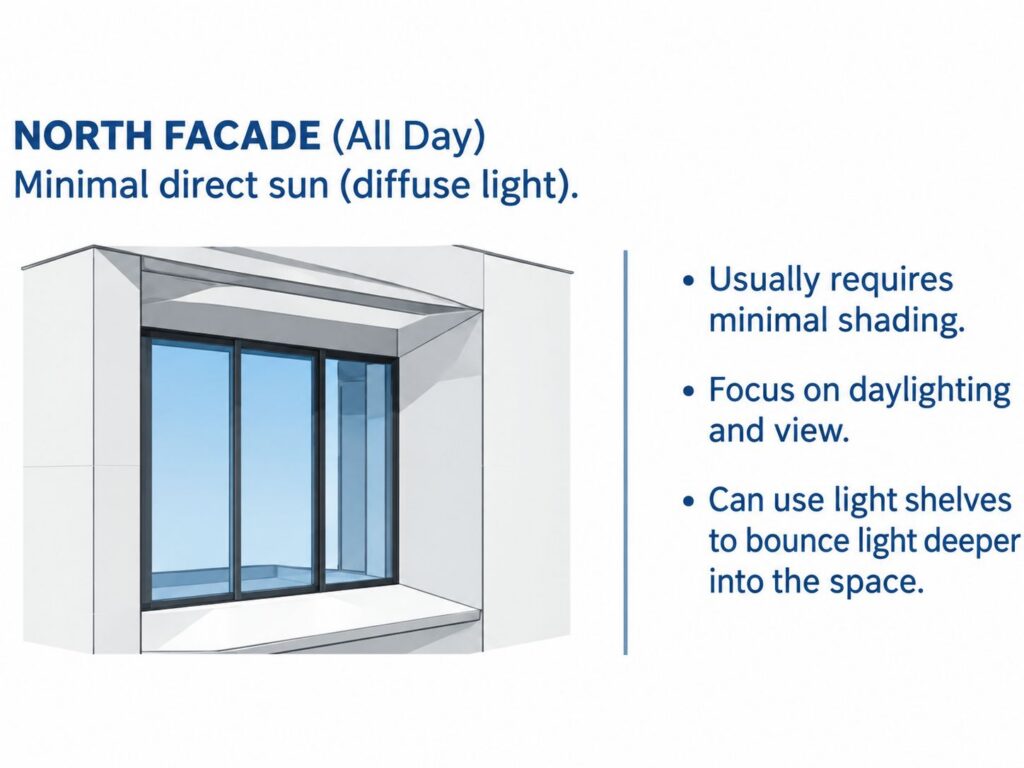
Illustration of Minimal Shading for North Elevation Facades
Shading Device Types: Geometry, Performance, and Appropriate Application
Horizontal Overhangs
The horizontal overhang is the most familiar and most geometrically straightforward passive shading element. It operates by projecting a horizontal plane above the glazing that casts a shadow onto the glazing surface when the sun is above the cutoff altitude defined by the overhang’s projection-to-height ratio – the ratio of the overhang depth to the distance from the overhang’s underside to the bottom of the glazed opening.
The key design parameters for a horizontal overhang are:
- Projection depth: The horizontal distance the overhang extends beyond the façade plane. Greater depth provides a lower solar cutoff angle, blocking the sun for more hours of the day and more months of the year. Depth must be balanced against structural implications, daylighting impact, and the risk of over-shading during transition seasons.
- Height above glazing sill: The vertical distance from the overhang’s underside to the bottom of the glazed opening. A deeper window-head-to-sill dimension allows a more modest overhang projection to achieve the same cutoff angle.
- Reveal and setback: How far the glazing is set back from the façade plane. Even modest setbacks — 6 to 12 inches in a window-wall or punched opening condition — contribute meaningfully to self-shading on south-facing façades.
From an enclosure standpoint, horizontal overhangs also serve as secondary water management elements, directing water away from the glazing-to-wall interface and reducing the driving rain exposure of the sill and perimeter conditions below. This enclosure benefit compounds the solar control function and should be factored into the cost-benefit evaluation of adding or extending overhangs. The primary limitation of horizontal overhangs — as discussed above — is their ineffectiveness on east and west façades, where low-angle sun passes beneath even deeply projected elements.
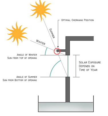
Horizontal Overhang Geometry Diagram – Defining Projection Depth and Solar Cutoff Angle
Vertical Fins
Vertical fins are the primary tool for shading low-angle sun on east- and west-facing façades. Where horizontal overhangs respond to solar altitude, vertical fins respond to solar azimuth – the compass bearing of the sun relative to the façade. A vertical fin projects perpendicular to the façade plane (or at an angle to it) and casts a shadow across the glazing surface when the sun’s azimuth is beyond the cutoff angle defined by the fin’s projection relative to the glazing width.
For east-facing façades, vertical fins on the south side of each glazed bay block the afternoon sun that arrives from the south-southeast after mid-morning; for west-facing façades, fins on the north side of each bay block the morning sun arriving from the north-northwest. The precise fin geometry – projection, spacing, and orientation angle – must be calibrated to the specific latitude and the hours of the day for which shading is desired, typically using solar angle calculations or energy modeling tools.
Vertical fins introduce greater architectural and structural complexity than horizontal overhangs, as they must be attached to the façade framing or primary structure, weather-sealed at their penetrations, and detailed to manage water at their interfaces with the enclosure. They are also less effective at blocking diffuse sky radiation and may require combination with a low-SHGC glazing to manage the diffuse component of east and west solar loads.
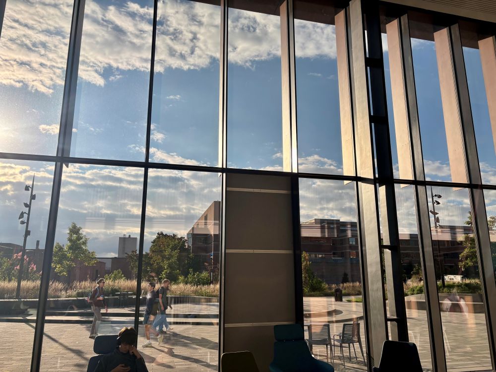
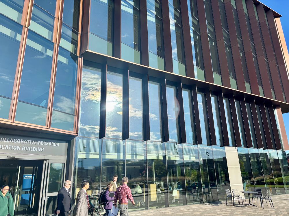
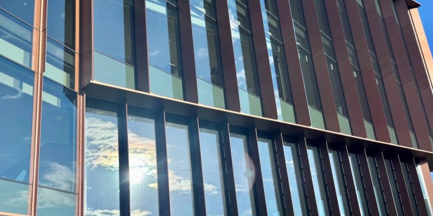
Vertical Fins Providing Protection from East Elevation Low-Angle Solar Radiation While also Enhancing the Architectural Appeal of the Penn State ECoRE Building. (This Elevation is Also Equipped with Automated Interior Shading Devices)
Egg-Crate and Combined Louver Systems
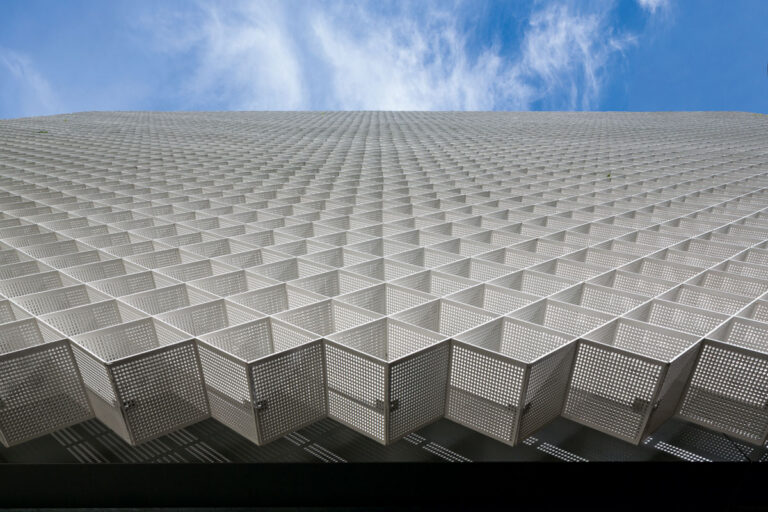
For façades that receive significant solar loading from multiple angles – southeast or southwest orientations, or buildings at latitudes where east and west exposures experience both low-angle and moderate-altitude sun during shoulder seasons – combined horizontal and vertical shading elements are often required. These systems, sometimes referred to as egg-crate configurations, integrate horizontal overhangs and vertical fins into a single grid-like assembly that controls both altitude and azimuth simultaneously.
Egg-crate systems are among the most effective passive shading configurations available, but they carry the highest cost, weight, and structural attachment complexity. Their cell geometry must be carefully optimized: cells that are too deep over-shade the glazing and compromise daylighting quality and view; cells that are too shallow fail to achieve meaningful solar load reduction during peak conditions. Parametric solar analysis – evaluating shading performance across the full annual sun path at the project’s latitude – is the appropriate design tool for optimizing combined shading geometry, and it should be performed in coordination with the glazing selection to ensure that the combined system achieves the project’s energy and comfort targets.
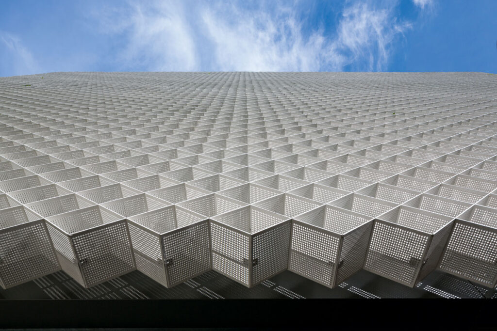
Egg-Crate Combined Shading System Applied to Façade to Provide Solar Protection
Interior and Interstitial Shading
Interior shading – blinds, shades, and interior roller systems – is frequently the only shading strategy considered in value-engineered or cost-constrained projects. It is also the least effective from an energy standpoint. Interior shading intercepts solar radiation after it has already crossed the glazing plane and entered the building as heat. Even a highly reflective interior blind that returns much of the incident radiation back through the glazing has already allowed the solar energy to heat the interior air and surfaces before it can be rejected.
The SHGC reduction achievable with interior shading is significantly lower than what the same shading material achieves in an exterior or interstitial position. Exterior shading, by intercepting radiation before it reaches the glazing, can reduce effective solar heat gain by 70 to 90 percent; interior shading typically achieves 20 to 40 percent reduction at best. Interstitial shading – motorized blinds or louvers installed within the cavity of a double-skin façade or between the glazing lites of a specialized triple-lite system – achieves intermediate performance while protecting the shading element from weather and wind loading. It is a viable strategy for high-performance projects where exterior shading is architecturally or structurally constrained, but it introduces significant fabrication complexity and maintenance access requirements.
Daylighting Design: Balancing Solar Control and Light Quality
Shading design cannot be evaluated in isolation from daylighting – the use of natural light to illuminate building interiors, reduce electric lighting energy use, and support occupant wellbeing. The tension between solar control and daylighting is the central design challenge of any shading strategy: a shading device that effectively eliminates direct beam radiation may also substantially reduce the diffuse daylight available in the interior, increasing reliance on electric lighting and potentially negating the energy savings achieved by reducing cooling load.
This tension is not inherent – it is a product of poorly calibrated shading geometry. Well-designed shading systems discriminate between direct beam radiation and diffuse sky radiation, blocking the former while preserving access to the latter. Horizontal overhangs, for example, block direct beam radiation arriving at high altitude while leaving the diffuse sky dome above the shading plane fully visible from the interior – maintaining a view of the sky and its associated daylight flux. Vertical fins on east and west façades block direct beam radiation from low-angle morning and afternoon sun while preserving the diffuse sky radiation arriving from other directions.
Daylight Metrics and Their Implications for Shading Design
The metrics used to evaluate daylighting performance have evolved significantly in recent years, moving away from simple point-in-time illuminance calculations toward climate-based, annual metrics that capture the full range of sky conditions throughout the year. The two most commonly used annual metrics are:
- Spatial Daylight Autonomy (sDA): The percentage of floor area that achieves a minimum illuminance threshold (typically 300 lux) for a minimum percentage of occupied hours (typically 50 percent) over the course of a year. LEED v4 and IES LM-83 use sDA as a primary daylighting metric. Higher sDA values indicate that more of the space is adequately daylit without supplemental electric lighting for more of the occupied year.
- Annual Sunlight Exposure (ASE): The percentage of floor area that receives more than 1,000 lux of direct sunlight for more than 250 hours per year — a proxy for excessive glare and thermal discomfort risk from direct beam penetration. ASE is a ceiling metric: lower is better, and LEED v4 requires ASE not to exceed 10 percent of the regularly occupied floor area. A shading strategy that achieves good sDA while keeping ASE below the threshold has successfully balanced daylight quality against direct solar penetration.
These metrics are evaluated using climate-based daylight modeling (CBDM) tools – simulation environments such as Radiance, Grasshopper with Honeybee, or Autodesk Forma – that use actual annual weather and sky condition data for the project location. CBDM analysis should be performed iteratively with shading geometry optimization: the shading design that minimizes ASE without compromising sDA is the design target, and it can only be identified through simulation rather than rule-of-thumb.
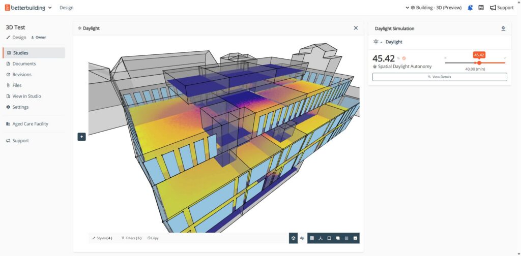
Daylight Modeling Software for Evaluation of Climate-Based Daylighting
Glare Control
Direct glare from beam sunlight penetrating the glazing plane is among the most persistent occupant comfort complaints in glazed commercial and multi-family buildings. Glare is distinct from solar heat gain: a spectrally selective low-E glazing can admit substantial visible light while rejecting near-infrared radiation, achieving low SHGC and high visible transmittance – but if direct beam sunlight reaches occupant work surfaces or seating areas, the high visible transmittance is itself the source of the complaint. Daylight quality requires diffuse illumination, not beam sunlight.
Shading devices that eliminate direct beam penetration – correctly sized for the relevant sun angles at the project latitude – are the most reliable glare control strategy. Interior solutions such as roller shades and automated blind systems can address residual glare from shading gaps or from diffuse sky conditions, but they do so at the cost of daylight quality and typically require occupant intervention or automated controls to deploy at the right moments. Passive exterior shading that prevents beam penetration geometrically is inherently more reliable than occupant-dependent interior controls.
Energy Code and LEED Context
The energy performance implications of shading design are captured in energy modeling tools through the application of shading multipliers and explicit geometric shading surfaces. When shading design is optimized in coordination with glazing selection and energy modeling, the combined effect on peak cooling load and annual energy use can be substantial: well-executed south-facing overhangs in the DC Metro and Atlanta markets can reduce peak cooling load contribution from south-facing glazing by 30 to 60 percent compared to unshaded conditions with the same glazing.
From a code compliance standpoint, the IECC and ASHRAE 90.1 both permit the energy performance of shading devices to be credited in whole-building energy modeling approaches. Shading devices that are modeled and verified as permanent, fixed building elements – with documented geometry and projection ratios — can be credited toward the fenestration performance path, potentially permitting higher glazing SHGC values than would otherwise be allowed under the prescriptive path.
Under LEED v4 and v5, both the Daylight credit (which uses sDA and ASE) and the Optimize Energy Performance credit reward integrated shading and glazing strategies. The Daylight credit in particular – which requires sDA ≥ 55 percent and ASE ≤ 10 percent for the base threshold – effectively mandates the kind of coordinated shading and glazing analysis described in this article, as it is difficult to achieve both metrics without deliberate shading design on east, south, and west façades.
Integration with the Building Enclosure
Shading elements are not independent of the building enclosure – they attach to it, penetrate it, and in many cases directly influence the performance of the control layers they pass through. Several enclosure integration considerations warrant attention in the design of any exterior shading system:
- Structural attachment and thermal bridging: Exterior shading elements must be attached to the building structure or façade framing, and their attachment brackets represent point thermal bridges through the continuous insulation plane. The same principles that govern cladding attachment thermal bridging – discussed in the August installment on thermal bridging – apply here. Thermally broken bracket systems, fiberglass or composite attachment arms, and careful detailing of the penetration through the ci plane are required to prevent the shading attachment from degrading the thermal envelope.
- Air and water barrier continuity: Where shading support arms or anchor plates penetrate the air and water control layers of the enclosure, the penetrations must be sealed to maintain control layer continuity. Failed sealant at shading attachment penetrations is a common source of water infiltration at the façade plane – a failure mode that is difficult to diagnose and remediate after construction because the leak path is concealed behind the cladding system.
- Drainage and water management: Horizontal shading elements accumulate water and debris and must be detailed to drain freely without directing water back toward the façade or allowing ponding at the attachment points. Weep provisions at the outer edge of overhangs, sloped top surfaces, and clearance between the shading element’s underside and the glazing head are standard detailing requirements.
- Maintenance access: Exterior shading elements require periodic inspection, cleaning, sealant maintenance, and occasional replacement of finishes or mechanical components (in the case of motorized systems). Access provisions – whether via building maintenance unit (BMU) equipment, davit points, or walkable surfaces at horizontal elements – must be coordinated at the design stage rather than resolved after the façade is complete.
Why This Matters
Radiation-control glazing and passive shading are not competing strategies – they are complementary tools that address different portions of the solar load management problem. Glazing SHGC controls the fraction of incident radiation that becomes heat gain; shading geometry controls how much radiation is incident on the glazing in the first place. Used together, they allow design teams to pursue generous, glazed façades with high visible transmittance and low cooling loads – without the compromise of heavily tinted glass that darkens interiors and suppresses daylighting quality.
The key discipline is orientation specificity. A single shading strategy applied uniformly across all elevations of a building will perform well on one or two façades and poorly on the others. Effective passive shading design requires that the solar geometry of each orientation be evaluated independently, that the appropriate shading typology be selected for each exposure, and that the shading geometry be optimized against the actual sun path at the project’s latitude — not generalized from precedent or assumed from visual proportion.
- A glazing specification controls what fraction of incident solar energy enters the building.
- A shading strategy controls how much solar energy is incident in the first place.
- The enclosures that perform best use both – calibrated to the specific geometry of each façade orientation.
What’s Next in Enclosure Insights
In the next installment of Enclosure Insights, we turn from the strategies that control solar loads at the façade plane to a less visible but equally consequential mechanism of enclosure performance: dynamic hygrothermal storage. Building materials do not simply resist the flow of heat and moisture – they absorb, retain, and release both in response to changing conditions, buffering the enclosure against the thermal and moisture peaks that drive energy demand, condensation risk, and occupant discomfort. Understanding how thermal mass and moisture-buffering capacity work, which materials contribute most meaningfully to each, and how these properties are accounted for in enclosure design and energy modeling is the next step in building a complete picture of high-performance enclosure behavior.
SK&A’s Building Enclosure Consulting + Waterproofing team brings decades of experience and specialized technical expertise to aid in the design and construction of new buildings, as well as the evaluation and maintenance of existing buildings. Learn more.