Authored by SK&A Principal Justin Long, PE, RBEC, BECxP. Follow Justin on Linked In.
Thermal Bridging: The Hidden Tax on Enclosure Performance
Last month’s Enclosure Insights examined high-performance insulation – how it is selected, where it should be located within an assembly, and the risks of getting either wrong. We closed with this takeaway: a high-performance enclosure gets both the amount and the placement of insulation right. This month, we examine the mechanism that most commonly undermines both: thermal bridging.
Thermal bridges are among the most consequential – and most frequently underestimated – performance issues in commercial and multi-family building enclosures. They are responsible for energy losses that exceed what nominal R-value calculations predict, condensation at locations that assembly cross-sections do not flag, and long-term durability problems that are often attributed to other causes. Understanding what thermal bridges are, where they occur, and how to address them is foundational to enclosure design that performs as intended.
What Is a Thermal Bridge?
A thermal bridge is any element within or penetrating a building enclosure assembly that conducts heat more readily than the surrounding insulated assembly. Because heat flows along the path of least resistance, these higher-conductivity elements – steel studs, concrete slabs, shelf angles, structural connections, fasteners, window frames – carry a disproportionate fraction of the total heat transfer across the envelope, effectively “short-circuiting” the insulation layer.
The practical consequence is a gap between nominal R-value and effective R-value. Nominal R-value is what the insulation product achieves in isolation, measured under laboratory conditions. Effective R-value is what the assembled system actually delivers in service, accounting for the full thermal performance of all components — including the bridges. The difference between the two is often substantial, and in poorly detailed assemblies it can be dramatic.
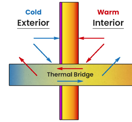
Graphic Depiction of a Thermal Bridge – Heat Flowing Through Element Penetrating Through Thermal Envelope
Thermal bridges are typically categorized by their geometry:
- Linear thermal bridges: Occur along edges and junctions – slab edges, parapet bases, shelf angles, window perimeters, and transitions between assembly types. Their heat loss is quantified by a linear thermal transmittance value, expressed as ψ (psi) in W/(m·K) or Btu/(hr·ft·°F).
- Point thermal bridges: Occur at discrete locations – structural connections, through-bolts, fasteners penetrating the thermal control layer, and canopy or cantilevered element attachments. Their heat loss is quantified by a point thermal transmittance value, expressed as χ (chi).
- Repeating thermal bridges: Occur at regularly spaced framing members – steel studs, metal Z-girts, hat channels, and concrete columns in curtain wall assemblies. Their cumulative effect is captured in the ASHRAE zone method or isothermal planes method for calculating clear-field wall U-factors.
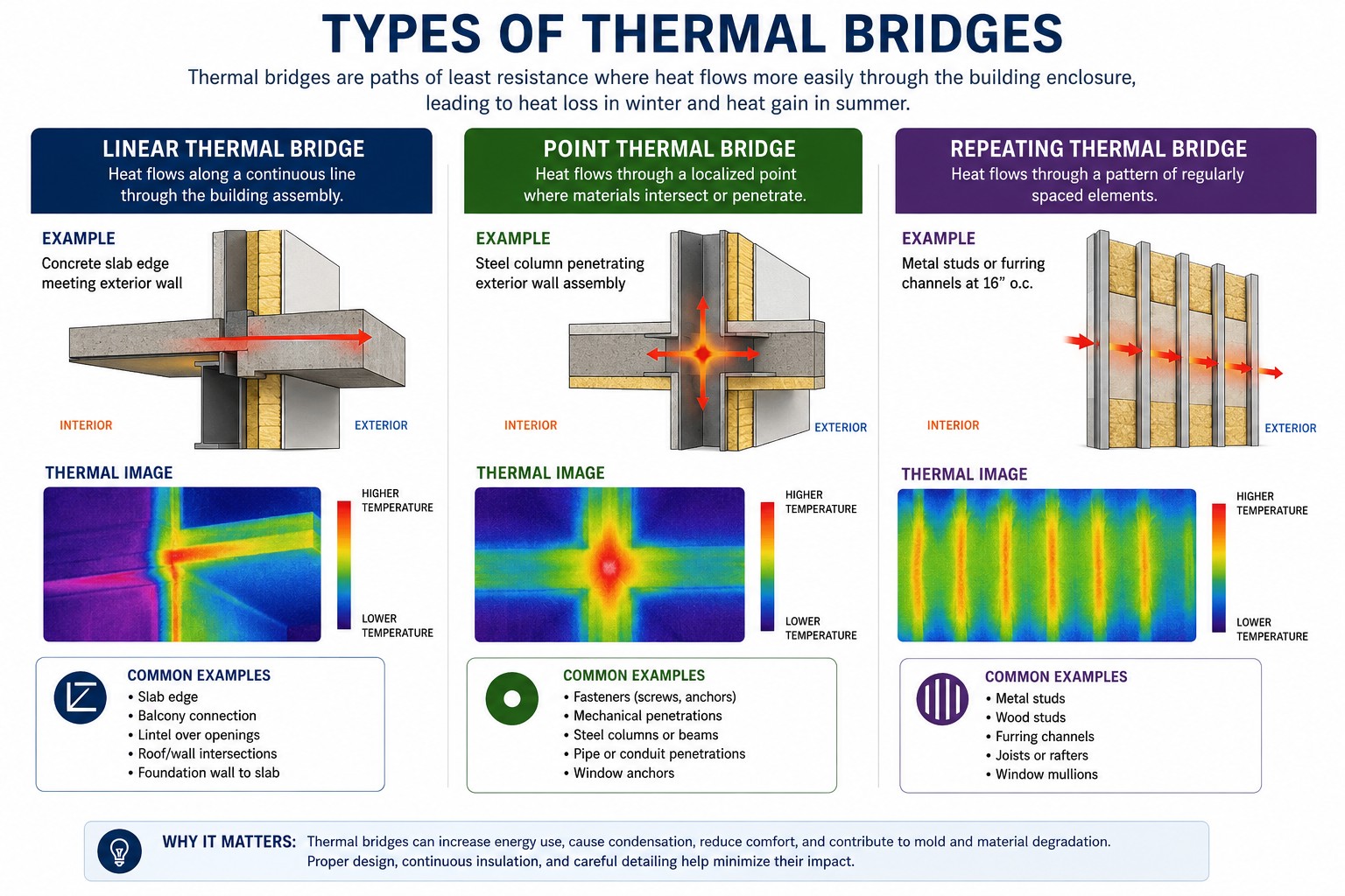
Illustration of Linear, Point, and Repeating Thermal Bridge Typologies in a Commercial Wall Assembly
How Thermal Bridges Reduce Effective R-Value
The reduction in effective R-value attributable to thermal bridging varies significantly depending on the thermal conductivity of the bridge material and the geometry of its penetration through the thermal envelope. Steel – the most common structural framing material in commercial and mid-rise multi-family construction – has a thermal conductivity approximately 400 times higher than wood and 1,500 times higher than typical mineral wool insulation. Even when a steel element represents a small fraction of the total wall area, its contribution to overall heat transfer is outsized.
The ASHRAE Handbook of Fundamentals provides a framework for calculating the effective U-factor of assemblies with repeating thermal bridges using the parallel-path method (for well-separated framing) and the isothermal planes method (for closely spaced or more conductive bridges). For complex assemblies with multiple bridge types and geometries, two-dimensional finite element analysis (2D FEA) – available through software tools such as THERM – provides the most accurate results.
To illustrate the magnitude of the effect, consider a common commercial exterior wall assembly: 6” metal stud framing at 16” o.c. with R-21 cavity insulation, sheathing, and an exterior brick veneer – but no continuous insulation outboard of the studs. The nominal R-value of the cavity insulation is R-21. The effective clear-field R-value of the full assembly, accounting for the thermal bridging of the light gauge steel studs, is typically R-9 to R-11 – a reduction of 35 to 50 percent. Reducing to 4” studs with R-13 cavity insulation and adding R-7.5 continuous insulation outboard of the framing recovers a substantial portion of this penalty, typically raising the effective assembly R-value to R-15 to R-17.
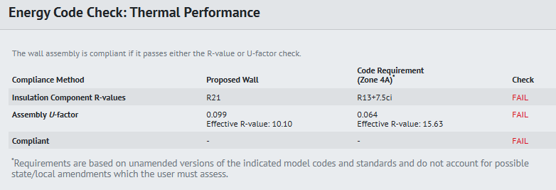
Comparison of Nominal R-Value vs. Effective R-Value for Metal-Stud Wall Assemblies With and Without Continuous Insulation
Common Thermal Bridge Locations in Commercial & Multi-Family Construction
Thermal bridges are not evenly distributed across a building enclosure. They concentrate at specific locations that are dictated by structural and construction realities – the same locations where the structural system must extend through the enclosure, where floors terminate at the exterior face, and where the enclosure must be penetrated or interrupted to accommodate the building’s program. The following are the most significant and commonly encountered bridge locations in commercial and multi-family construction.
Slab Edges and Floor-Line Conditions
The concrete floor slab is typically the most significant single source of thermal bridging in multi-family and mixed-use construction. Where a concrete slab extends to or near the exterior face of the building – as is standard in cast-in-place and precast concrete construction – it creates a high-conductivity pathway that bypasses the insulation in the wall assembly above and below.
In a mid-rise concrete building without slab edge insulation or a thermal break, the slab edge can account for 20 to 40 percent of the total wall heat loss at that floor line, despite representing a fraction of the total wall area. It also produces a cold interior surface at the slab soffit near the exterior wall – a reliable location for condensation and mold growth in buildings with elevated interior humidity, such as residential occupancies.
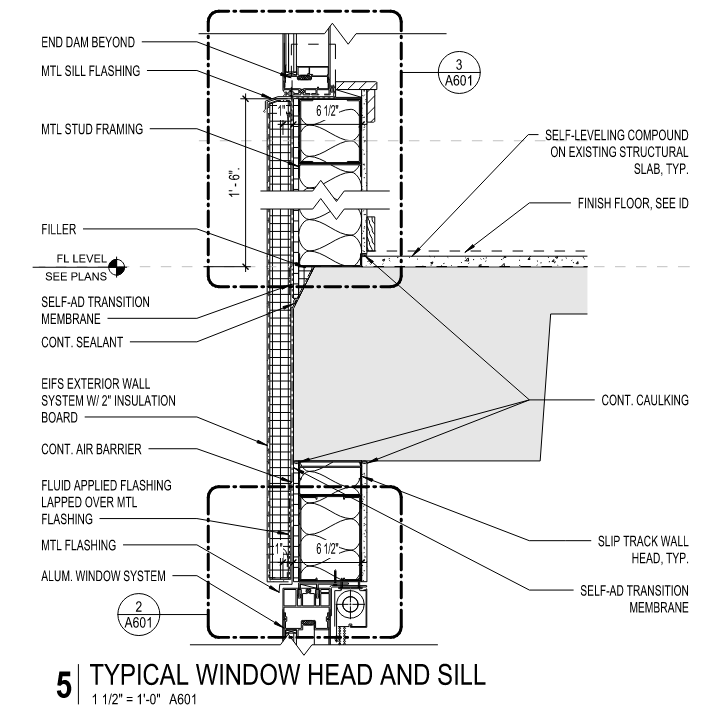
Typical Concrete Slab Edge Condition with EIFS Façade
Shelf Angles and Masonry Veneer Supports
In construction types where masonry veneer – brick, stone, or architectural concrete masonry – is carried by structural steel shelf angles anchored to the building’s primary structure, the shelf angle itself constitutes a significant thermal bridge. Shelf angles are typically located at each floor level, penetrating or interrupting the continuous insulation plane that would otherwise be maintained across the wall assembly.
The shelf angle bridge is compounded by the geometry of the masonry veneer cavity: the angle must be large enough to carry the masonry load, and its attachment must penetrate through the insulation to reach the backup structure. Each attachment is itself a point thermal bridge.
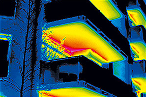
When shelf angles are not thermally isolated from the primary structure – through the use of thermal isolation or “stand-offs” at the mounting interface – they transmit heat directly from the conditioned interior to the exterior, cooling the interior face of the backup wall at each floor line and creating a pattern of thermal bridges that is readily visible on infrared thermography.
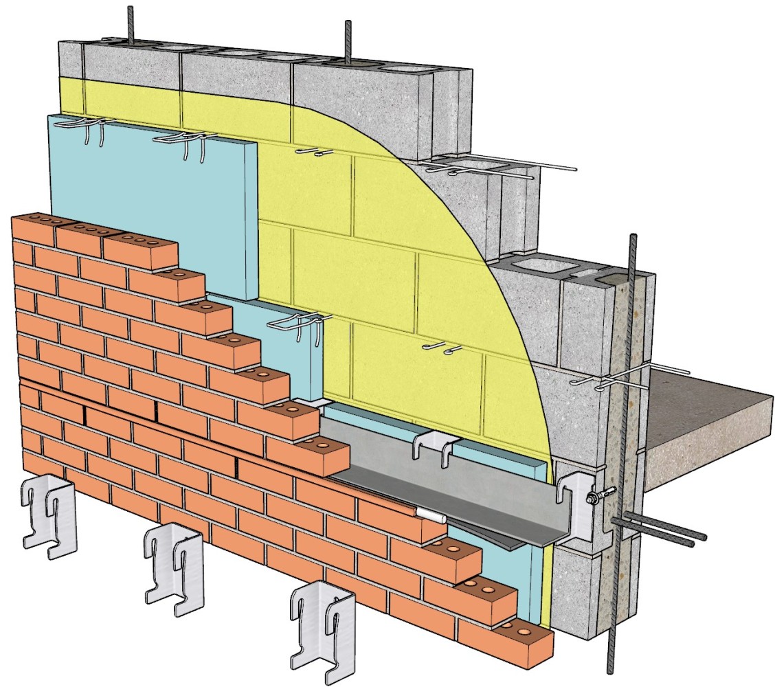
Detail Illustrating Shelf Angle with Stand-off Brackets to Eliminate Thermal Bridging via Continuous Insulation
Balconies and Cantilevered Slabs
Cantilevered concrete balconies represent one of the most severe thermal bridge conditions encountered in multi-family construction. A cast-in-place balcony slab that is continuous with the interior floor slab – the most common construction method – creates a wide, uninterrupted concrete conduction pathway from the heated interior to the cold exterior. The interior surface temperature at the base of the balcony connection can drop to near or below the dew point under cold-weather conditions, producing persistent condensation and the potential for mold growth at the base of the exterior wall in the room adjacent to the balcony.
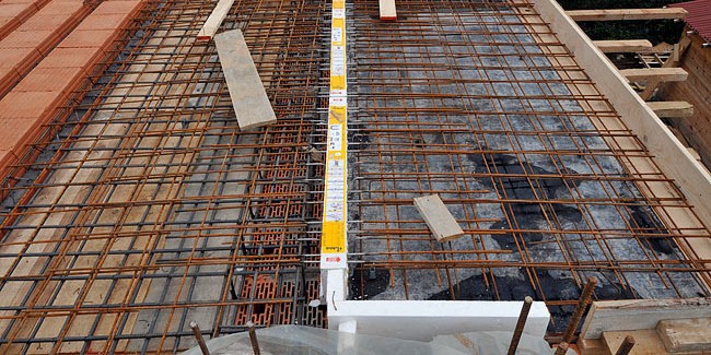
Addressing the balcony thermal bridge requires the use of a structural thermal break element – a prefabricated connector assembly that transfers structural loads (gravity, wind, seismic) across the insulation plane while providing a low-conductivity thermal separation between the interior and exterior slab sections. Products such as Schock Isokorb and similar structural thermal breaks are now commonly specified in high-performance multi-family construction, though they require careful coordination between the structural engineer and enclosure consultant at the design stage.
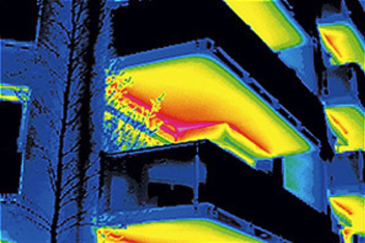
Infrared Thermography Image of Exterior Façade Showing Thermal Bridging at Cantilevered Concrete Balconies
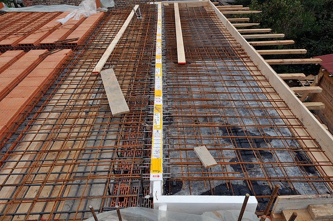
View Structural Thermal Break Element at Cantilevered Balcony Connection
Parapets
The parapet is a frequently overlooked but significant source of thermal bridging at the roof-to-wall transition. Where the roof insulation and wall insulation do not overlap and connect at the parapet, an uninsulated concrete or masonry parapet wall conducts heat from the conditioned building interior to the exterior at the roof line – a location where the temperature differential between interior and exterior is greatest during heating season.
A well-detailed parapet wraps the roof insulation over the top of the parapet and connects it to the wall’s continuous insulation, maintaining a continuous thermal envelope through the transition. There are also options for introducing thermal breaks at the base of the parapet wall construction.
Roof assemblies that terminate insulation at the parapet base – without introducing a thermal break or lapping insulation through the transition – leave a repeating thermal defect at every parapet along the building perimeter.
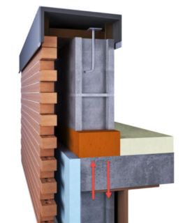
View of Thermal Break Introduced at Base of Parapet Wall
Metal Z-Girts, Hat Channels, and Cladding Attachment Systems
Many exterior cladding systems – metal panel, fiber cement, composite panel, and similar products – are attached to the building structure through a secondary framing system of steel Z-girts or hat channels spanning across the continuous insulation plane. Each girt or channel penetrates the insulation, creating a repeating linear thermal bridge across the full wall area.
The thermal bridging penalty of Z-girt systems is well-documented. ASHRAE 90.1 and related enclosure research have demonstrated that a standard 16-gauge steel Z-girt at 24” o.c. can reduce the effective R-value of the outboard insulation layer by 30 to 50 percent relative to its nominal value. This means that an assembly specified to achieve R-15 ci through a Z-girt system may deliver only R-7 to R-10 in effective clear-field performance – a result that may not comply with prescriptive code requirements even when the nominal ci specification appears to.
Mitigation strategies for Z-girt bridging include the use of thermally broken girt systems (which incorporate a low-conductivity spacer between the steel girt and the primary structure), vertical girt orientation (which reduces the linear bridge length per unit of wall area), fiberglass or composite girts (which eliminate the steel conduction path entirely), and rainscreen clip-and-rail systems (which attach at discrete points rather than continuously, substantially reducing the thermal bridge area ratio).
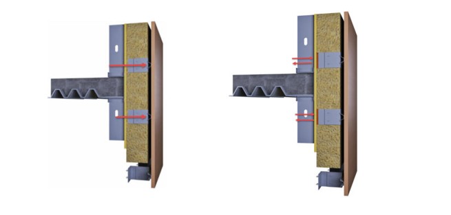
Comparison of Z-Girt Thermal Bridge vs. Thermally Broken Cladding Attachment System
Fenestration Frames
Fenestration frames – aluminum storefront, curtain wall mullions, and window frames – are inherent thermal bridges at every opening in the enclosure. Aluminum has a thermal conductivity approximately 1,000 times higher than glass and is several orders of magnitude more conductive than the surrounding insulated wall assembly. Even thermally broken aluminum frames, which incorporate a low-conductivity polyamide or polyurethane break between the interior and exterior frame sections, represent a meaningful conduction pathway relative to the adjacent high-R wall assembly.
The perimeter condition at the interface between the fenestration frame and the surrounding wall assembly is also a critical bridge location. Where the fenestration frame bears directly on or adjacent to the primary structure without insulation wrapping the rough opening – a common condition in masonry or concrete construction – a cold corner is produced at the interior sill and jamb that is vulnerable to condensation and mold growth.
Structural Penetrations and Mechanical Supports
Any element that penetrates the thermal envelope of the enclosure – structural steel beams, pipe sleeves, conduit, mechanical equipment supports, facade tie-back anchors, and similar elements – constitutes a point thermal bridge. These penetrations are individually smaller in their thermal impact than the linear bridges previously discussed, but they can be numerous in complex commercial buildings and their cumulative effect warrants attention in high-performance enclosure design.
Strategies to Eliminate or Mitigate Thermal Bridges
Thermal bridge mitigation is most effective and most cost-efficient when addressed in the design phase. The strategies available fall into three broad categories: elimination (removing the bridge from the assembly), isolation (interrupting the conduction path with a low-conductivity element), and compensation (offsetting the heat loss with additional insulation elsewhere in the assembly). The following summarizes the principal strategies for each bridge type.
Continuous Insulation Outboard of the Structure
The single most effective strategy for reducing repeating thermal bridges at framing members is the placement of continuous insulation (ci) outboard of the primary structural framing plane. Because ci is not penetrated by framing members, it maintains its full nominal R-value across the framing bays and significantly reduces – though does not eliminate – the thermal penalty of the framing itself.
The effectiveness of ci as a thermal bridge mitigation strategy is directly proportional to its thickness relative to the total assembly R-value. Assemblies with a higher ratio of outboard ci to cavity insulation have lower framing correction factors and higher effective R-values. This is why ASHRAE 90.1 and the IECC have progressively increased minimum ci requirements in higher climate zones – the ci is doing double duty as both an R-value contributor and a thermal bridge mitigator.
Structural Thermal Breaks
Where a structural element must cross the thermal control layer – at balconies, shelf angles, canopies, facade connections, etc. – the most effective mitigation is a prefabricated structural thermal break element. These systems transfer structural loads through a material of substantially lower thermal conductivity than steel or concrete – typically a fiberglass-reinforced nylon or high-density polyurethane composite – while maintaining the required load path across the insulation plane.
Structural thermal breaks require close coordination between the structural engineer of record, the enclosure consultant, and the manufacturer, as the elements must be sized for the specific load combinations at each connection and detailed to maintain both the air barrier and thermal control layer continuity through the transition. When properly integrated, they can reduce the thermal transmittance at structural connections by 75 to 90 percent relative to an unbridged cast-in-place condition.
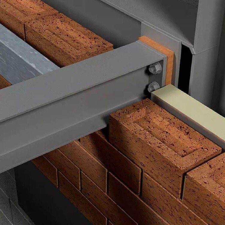
Armatherm Structural Thermal Break at Bolted Steel Connection
An emerging category of thermal bridge mitigation worth noting is fluid-applied insulated coatings, such as Tnemec’s aerogel-based Aerolon product that can be spray- or brush-applied directly to exposed structural elements – steel beams, Z-girts, shelf angle bearing surfaces, pipe penetrations, and similar point and linear bridge locations. These coatings are formulated with aerogel, one of the lowest-conductivity solid materials available, and are marketed as a non-structural alternative to prefabricated thermal break pads or shims at locations where conventional break elements are difficult to detail or cost-prohibitive to install. Their primary advantage is accessibility: they can be applied in the fabrication shop or in the field, and they accommodate irregular geometries that rigid thermal break products cannot. As with any thermal bridge mitigation strategy, the performance of fluid-applied coatings should be evaluated against documented test data – including measured linear or point thermal transmittance values – rather than nominal claims, and their use should be coordinated with the enclosure consultant to confirm that they achieve the required improvement to effective assembly R-value.
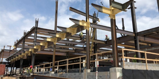
Tnemec’s Aerolon Applied at Structural Steel Canopy Framing – Extending Out at Exterior and through to the Interior Steel
Thermally Broken Cladding Attachments
For cladding systems that require a secondary framing layer across the continuous insulation plane, thermally broken attachment systems substantially reduce the girt bridging penalty. Options include:
- Thermal spacer / isolator pads: Low-conductivity pads inserted between a conventional steel Z-girt and the primary structure, breaking the direct steel-to-steel conduction path. Effective but limited in the thermal improvement achievable, as the girt itself remains a full bridge across the insulation.
- Composite and fiberglass girts: Z-girts and hat channels fabricated from fiberglass-reinforced polymer or structural composite materials eliminate the steel conduction path entirely. These products are now available in standard profiles compatible with conventional cladding attachment details and offer dramatic reductions in linear thermal transmittance.
- Clip-and-rail systems: Discrete attachment clips spaced at defined intervals, connected to horizontal rails that support the cladding panel. Because the thermal bridge area is concentrated at the discrete clips rather than distributed continuously along the full girt length, the overall bridging penalty is substantially reduced. When clips incorporate a thermally broken or composite bracket, effective ci R-values can be maintained at 80 to 90 percent of nominal.
Parapet and Roof-to-Wall Transition Detailing
Parapet thermal bridges are addressed through thermal breaks or insulation continuity at the roof-wall interface. Effective strategies include wrapping rigid board insulation over the top of the parapet and connecting it to the wall’s outboard ci layer, ensuring that the thermal envelope forms a continuous closed loop at the building perimeter. For concrete and masonry parapets, interior-face insulation applied to the parapet wall maintains the temperature of the parapet above the dew point under heating-season conditions, reducing condensation risk at the roof-to-wall transition.
Roof membrane terminations at the parapet also require coordination with the insulation strategy: the membrane must be continuous with the air and water control layers in the wall assembly, and the detail must accommodate thermal movement of the insulation and membrane system without creating gaps or punctures in the control layers.
Thermal Analysis and Enclosure Commissioning (BECx)
Tools such as THERM, leveraged during the design phase, allow enclosure consultants to calculate the actual linear and point thermal transmittance of proposed details, quantitatively compare mitigation strategies, and confirm that the effective assembly performance will meet code requirements and owner performance targets.
When incorporated into a Building Enclosure Commissioning (BECx) program, technical reviews of design documents provide an objective evaluation of the thermal envelope, to include thermal bridging conditions. Identification of such thermal bridges during design allows design teams the opportunity to eliminate, isolate, or compensate as appropriate before construction ever begins. During and after construction, infrared thermography is the primary field verification tool for identifying thermal bridges and verifying functional performance. Conducted under appropriate temperature differential conditions (typically a minimum of 18°F between interior and exterior), whole-building thermographic surveys can identify bridge locations, installation defects in the continuous insulation plane, and air leakage pathways that would otherwise remain concealed. Thermographic surveys provide an objective, documented record of as-built enclosure thermal performance.
Why This Matters
Thermal bridging is not a niche performance concern – it is a fundamental limitation on what a building enclosure can actually deliver relative to what its specifications predict. Buildings designed to meet prescriptive energy code requirements on the basis of nominal R-values may fall meaningfully short of those requirements in practice if thermal bridges are not identified, quantified, and mitigated in the design.
The consequences extend beyond energy performance. Cold interior surfaces at bridge locations are reliable sites for condensation, mold growth, and the occupant complaints and liability exposures that follow. In multi-family construction particularly, where interior humidity is elevated by occupancy and the building is expected to perform over decades, unaddressed thermal bridges are a source of recurring maintenance issues, envelope failures, and asset depreciation.
-
A building’s energy model assumes a continuous thermal envelope.
-
A building’s actual performance reflects every bridge that was left in it.
-
The gap between the two is where energy is lost, condensation forms, and enclosure durability is compromised.
What’s Next in Enclosure Insights
In the next installment of Enclosure Insights, we shift our focus to the enclosure’s most thermally vulnerable surface: glazing. We will examine radiation-control glazing technologies – how low-emissivity coatings, selective transmission spectra, and multi-pane assembly configurations work together to manage solar heat gain, minimize radiative heat loss, and maintain interior glass surface temperatures above the dew point. For buildings with significant glazed area, fenestration performance is often the single largest variable in enclosure thermal and comfort outcomes, and the selection and specification of glazing systems deserves the same rigor applied to opaque wall and roof assemblies.
SK&A’s Building Enclosure Consulting + Waterproofing team brings decades of experience and specialized technical expertise to aid in the design and construction of new buildings, as well as the evaluation and maintenance of existing buildings. Learn more.