Authored by SK&A Principal Justin Long, PE, RBEC, BECxP. Follow Justin on Linked In.
Glazing & Radiation Control: Engineering the Enclosure’s Most Vulnerable Surface
Last month’s Enclosure Insights examined thermal bridging – the conductive pathways that undermine the difference between an enclosure’s nominal and effective thermal performance. We closed with this takeaway: the gap between a building’s designed thermal envelope and its actual performance is where energy is lost, condensation forms, and durability is compromised. This month, we turn to the surface where that gap is widest by design: glazing.
Fenestrations are the enclosure’s most thermally vulnerable component. Even the highest-performing glazing assemblies available today deliver a small fraction of the thermal resistance of a code-minimum opaque wall – and for buildings with significant glazed area, fenestrations are frequently the single largest variable in enclosure energy, comfort, and condensation outcomes. Yet glazing selection is often treated as an architectural and aesthetic decision first, with thermal and solar performance verified late – or not at all. Understanding how heat actually moves through glazing, and how modern radiation-control glazing technologies manage it, is essential to specifying fenestrations with the same rigor applied to opaque wall and roof assemblies.
Why Glazing Is Different: Three Modes of Heat Transfer
Opaque enclosure assemblies resist heat flow primarily through conduction control – insulation interrupting the conductive path from interior to exterior. Glazing is fundamentally different, because all three modes of heat transfer are active and consequential:
- Conduction through the glass panes, the gas or air space between them, the edge spacer, and the frame.
- Convection within the sealed cavity of an insulating glass unit (IGU), where the gas fill circulates between the warm and cold panes, and at the interior and exterior glass surfaces.
- Radiation – both long-wave infrared radiation exchanged between the glass surfaces (and between the glazing and the room), and short-wave solar radiation transmitted directly through the assembly.
The third mode (radiation) is the one that distinguishes glazing from every other enclosure component – and the one that modern glazing technology is engineered to control. In a conventional double-glazed unit with uncoated glass, radiative exchange between the two panes accounts for approximately two-thirds of the total heat transfer across the cavity. And on the solar side, roughly half of the sun’s energy arrives as invisible near-infrared radiation – energy that contributes nothing to daylight but everything to cooling load. Radiation control – managing what the glazing emits, absorbs, reflects, and transmits across the electromagnetic spectrum – is therefore the central mechanism of high-performance fenestration design.
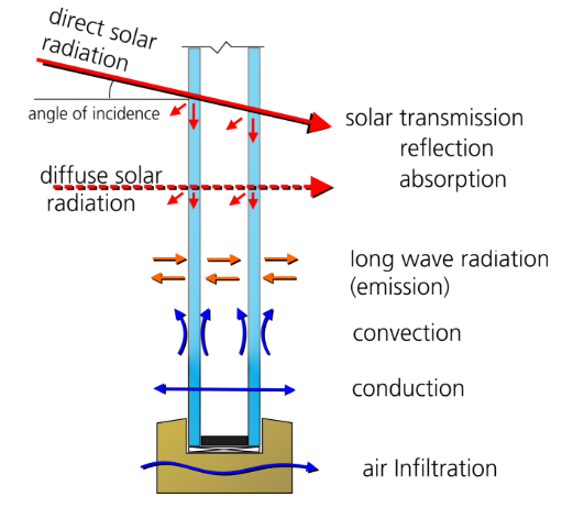
Heat Transfer Mechanisms Through an Insulating Glass Unit – Conduction, Convection, and Radiative Exchange (Photo: Fraunhofer IBP)
The Metrics That Define Fenestration Performance
Before examining the technologies themselves, it is worth grounding the discussion in the performance metrics by which fenestrations are specified, rated, and verified:
- U-factor: The overall heat transmission coefficient of the assembly, capturing conduction, convection, and long-wave radiative transfer. Lower is better. Rated per NFRC 100 for the whole product – glass, spacers, and frame together.
- Solar Heat Gain Coefficient (SHGC): The fraction of incident solar energy that enters the building – both directly transmitted and absorbed-and-reradiated inward. Rated per NFRC 200. In cooling-dominated climates, SHGC is typically the most consequential number on the schedule.
- Visible Transmittance (VT): The fraction of visible light transmitted through the glazing – the daylighting and view metric.
- Light-to-Solar-Gain ratio (LSG): VT divided by SHGC. This ratio quantifies spectral selectivity – how much daylight the glazing admits per unit of solar heat gain. Values above approximately 1.25 are generally considered spectrally selective.
- Condensation Resistance: Rated as a Condensation Resistance Factor (CRF) per AAMA 1503 or a Condensation Resistance (CR) index per NFRC 500. Higher values indicate warmer interior surface temperatures and greater resistance to condensation under a given interior humidity condition.
A critical distinction runs through all of these metrics: center-of-glass values versus whole-product values. Center-of-glass performance reflects the glazing makeup alone and is always the more flattering number.
Whole-product ratings account for the edge-of-glass zone and the frame – which, as last month’s discussion of fenestration frames as thermal bridges made clear, can degrade assembly performance substantially. Specifications should be written, and submittals reviewed, against whole-product NFRC ratings – not center-of-glass marketing values.
Low-Emissivity Coatings: Controlling Radiative Exchange
How Low-E Works
Every surface emits long-wave infrared radiation in proportion to its emissivity – a property ranging from 0 to 1 that describes how efficiently the surface radiates thermal energy. Uncoated glass has an emissivity of approximately 0.84, meaning it is a highly efficient radiator: a warm interior pane readily radiates heat across the IGU cavity to the cold exterior pane in winter, and a hot exterior pane radiates heat inward in summer.
A low-emissivity (low-E) coating is a microscopically thin, optically transparent layer – typically incorporating one or more layers of silver – deposited on a glass surface to suppress this radiative exchange. Modern sputtered coatings reduce surface emissivity to as low as 0.02 to 0.10, cutting the radiative component of heat transfer across the cavity by an order of magnitude. Because radiation is the dominant transfer mode across the cavity of an uncoated unit, the effect on overall U-factor is dramatic: as typical whole-product values, a clear double-glazed unit performs in the range of U-0.45 to U-0.50, while the same configuration with a soft-coat low-E surface and argon fill performs in the range of U-0.25 to U-0.30 – roughly the difference between R-2 and R-3.5 to R-4.
Hard-Coat vs. Soft-Coat
Low-E coatings are produced by two distinct processes with meaningfully different performance characteristics. Pyrolytic (“hard-coat”) coatings are applied to the glass surface during manufacture while the glass is still hot, fusing a metallic-oxide layer into the surface. They are durable, handleable, and suitable for exposed applications – but their emissivity is comparatively high, typically in the range of 0.15 to 0.20. Sputtered (“soft-coat” or MSVD) coatings are applied in a vacuum chamber after they’re manufactured, building up precisely controlled layers of silver and protective metal oxides. They achieve far lower emissivity and far better spectral selectivity, but the coating is delicate and must be protected within the sealed cavity of an IGU. Soft-coat products dominate commercial and multi-family specification today, and essentially all high-performance spectrally selective products are sputtered coatings.
Coating Placement: The Surface Numbering Convention
The performance of a low-E coating depends not only on its composition but on which surface of the IGU it occupies. Glazing surfaces are numbered from the exterior inward: in a double-glazed unit, surface #1 is the exterior face of the outboard lite, surface #2 is its interior face, surface #3 is the exterior face of the inboard lite, and surface #4 faces the room.
- Surface #2 placement – the standard configuration for solar-control low-E in cooling-dominated and mixed climates – intercepts solar radiation at the outboard lite, reflecting near-infrared energy back to the exterior before it crosses the cavity. This placement minimizes SHGC.
- Surface #3 placement – the classic “passive” low-E configuration for heating-dominated climates – allows more solar gain into the building while still suppressing long-wave radiative loss from the interior, retaining passive solar heat.
- Surface #4 (room-side) low-E – a hard-coat applied to the interior face of the inboard lite – further improves rated U-factor by reducing radiative exchange between the glass and the room. It carries an important caveat, however: by decoupling the interior glass surface from the room’s radiant environment, it lowers the interior glass surface temperature under winter conditions and can increase condensation risk. In humidified buildings and residential occupancies, fourth-surface low-E should be evaluated against the project’s condensation resistance requirements – not adopted solely for its U-factor benefit.
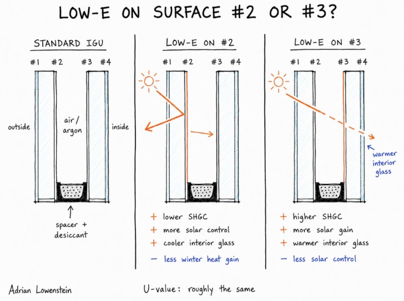
IGU Surface Numbering Convention and Low-E Coating Placement Strategies (Photo Credit: Adrian Lownestein: https://www.linkedin.com/feed/update/urn:li:share:7489295871591727104/)
Selective Transmission Spectra: Daylight Without the Heat
Solar radiation spans the ultraviolet, visible, and near-infrared portions of the spectrum – and only the visible portion contributes to daylighting. Early-generation tinted and reflective glazing reduced solar heat gain crudely, by attenuating the entire spectrum: less heat, but also less daylight, darker interiors, and higher lighting energy use. The signature achievement of modern coating technology is spectral selectivity – the ability to transmit the visible wavelengths while reflecting the near-infrared.
Spectrally selective coatings accomplish this through multiple discrete silver layers – double-silver and triple-silver coatings are now standard commercial offerings – each tuned to reflect progressively more of the near-infrared spectrum while preserving visible transmission. The practical result: contemporary triple-silver products deliver visible transmittance in the range of 60 to 70 percent with SHGC values in the range of 0.23 to 0.30, producing LSG ratios approaching or exceeding 2.0. For comparison, clear uncoated glass has an LSG near 1.0, and traditional bronze or gray tints fall well below it.
For cooling-dominated climates – including the hot-humid Southeast – spectral selectivity is the difference between glazing that fights the mechanical system and glazing that works with it. It permits generous, glazed area and daylight-driven design without the cooling-load penalty that the same glazed area would have imposed a generation ago.
It is also why SHGC and VT should always be specified together: an SHGC target achieved with a low-LSG product sacrifices daylight that a spectrally selective product would have preserved.
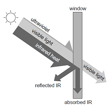
Graphic Depicting Spectral Selectivity
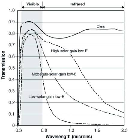
Spectral Transmittance Curves for Glazing with Three Different Low-E Coatings
(Photo Credit: Lawrence Berkeley National Laboratory)
Multi-Pane Assembly Configurations
Coatings control radiation; the assembly configuration controls conduction and convection. The two work together, and the performance of the complete unit depends on how they are combined.
Gas Fills and Cavity Optimization
Replacing the air in a sealed IGU cavity with argon – a denser, less conductive gas – reduces both conductive and convective transfer across the cavity, improving U-factor at modest cost. Argon’s thermal conductivity is roughly one-third lower than air, and it has become the default fill in low-E commercial units. Krypton performs better still and reaches its optimum in narrower cavities, which makes it valuable in triple-glazed units where overall unit thickness is constrained – though its cost premium is substantial. Cavity width itself is a design variable: too narrow and conduction dominates; too wide and convective circulation develops. The gas fill, cavity dimension, and coating strategy are optimized together, which is one more reason glazing makeups should be evaluated as complete systems rather than assembled à la carte from a schedule.
Warm-Edge Spacers
The spacer that separates the lites at the perimeter of an IGU is a linear thermal bridge in miniature – a direct conductive path between the panes at the coldest zone of the unit. Conventional aluminum box spacers produce a pronounced cold band at the edge of glass, and it is at this edge zone – particularly the bottom edge, where convective currents deposit the coldest interior air – that condensation reliably appears first. Warm-edge spacer systems, using stainless steel, thermoplastic, silicone foam, or composite construction, substantially reduce edge-of-glass heat loss and raise edge surface temperatures. In humidified and residential buildings, the spacer specification is a condensation-control decision as much as an energy decision.
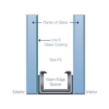
Typical Glass Cross-Section w/ Warm Edge Spacer
Triple Glazing and Suspended Films
Adding a third lite – or a suspended low-E-coated film within the cavity – introduces an additional insulating cavity and an additional coated surface, pushing whole-product U-factors into the range of 0.15 to 0.20 and below. Triple glazing also raises interior glass surface temperatures markedly, which improves both winter comfort near the glass and condensation resistance – benefits that matter in humidified buildings independent of the energy case. The trade-offs are weight, overall thickness, framing compatibility, and cost, all of which must be coordinated with the fenestration system early. Suspended-film products achieve much of the thermal benefit at a fraction of the weight, at the cost of specialized fabrication. Vacuum insulating glazing and dynamic (electrochromic) glazing are emerging categories worth watching, but multi-pane low-E assemblies remain the workhorses of current high-performance specification.
Interior Surface Temperature: The Condensation Connection
Threaded through each of the preceding topics is a performance outcome that receives far less specification attention than U-factor or SHGC yet generates a disproportionate share of post-occupancy complaints and enclosure investigations: interior surface temperature. Whenever any interior surface of the fenestration assembly – glass, edge zone, or frame – falls below the dew point of the adjacent interior air, condensation forms. Persistently, predictably, and in the same locations every cold morning.
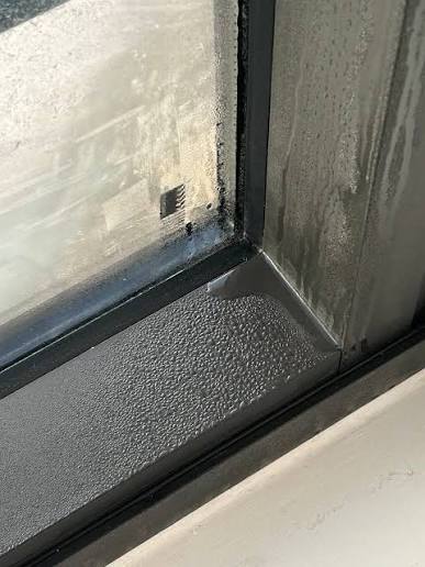
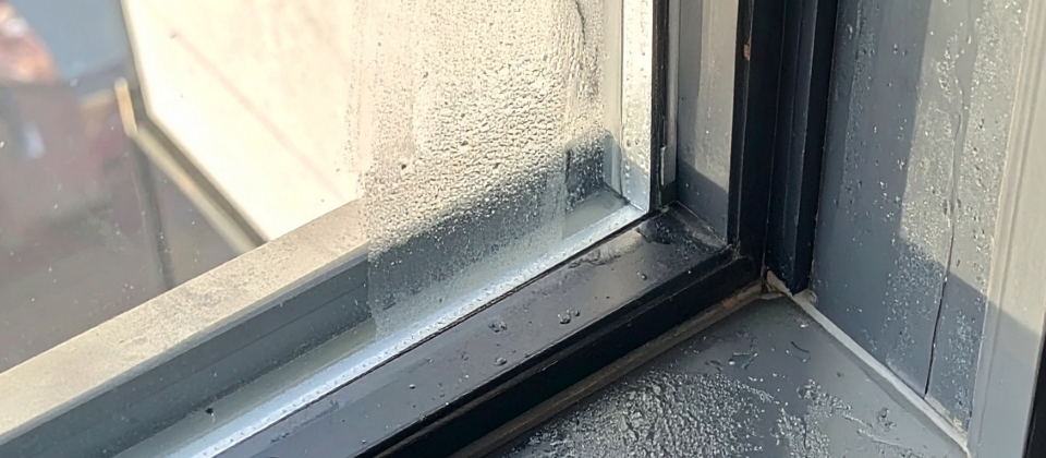
View of Interior Condensation at Fenestration Framing & Glazing
This is where the glazing discussion reconnects with last month’s thermal bridging discussion. The glazing makeup may perform admirably at center of glass while the aluminum frame and edge-of-glass zone – the assembly’s built-in thermal bridges – run cold enough to condense moisture throughout the heating season. Multi-family and hospitality occupancies, with their elevated interior humidity, are the most exposed; so are humidified museum, healthcare, and archival environments, where condensation resistance often governs the fenestration selection outright.
The tools for managing this risk are specification-stage tools: whole-product condensation ratings (CRF per AAMA 1503, CR per NFRC 500) specified against the project’s actual design interior humidity – not a default value; thermally broken or thermally improved framing; warm-edge spacers; and, where the humidity conditions warrant it, triple glazing. THERM modeling of the project-specific frame, spacer, and glazing combination – the same two-dimensional finite element analysis discussed last month for opaque assemblies – can predict interior surface temperatures at the actual design conditions and identify condensation risk before the fenestration is procured, rather than after the first winter.
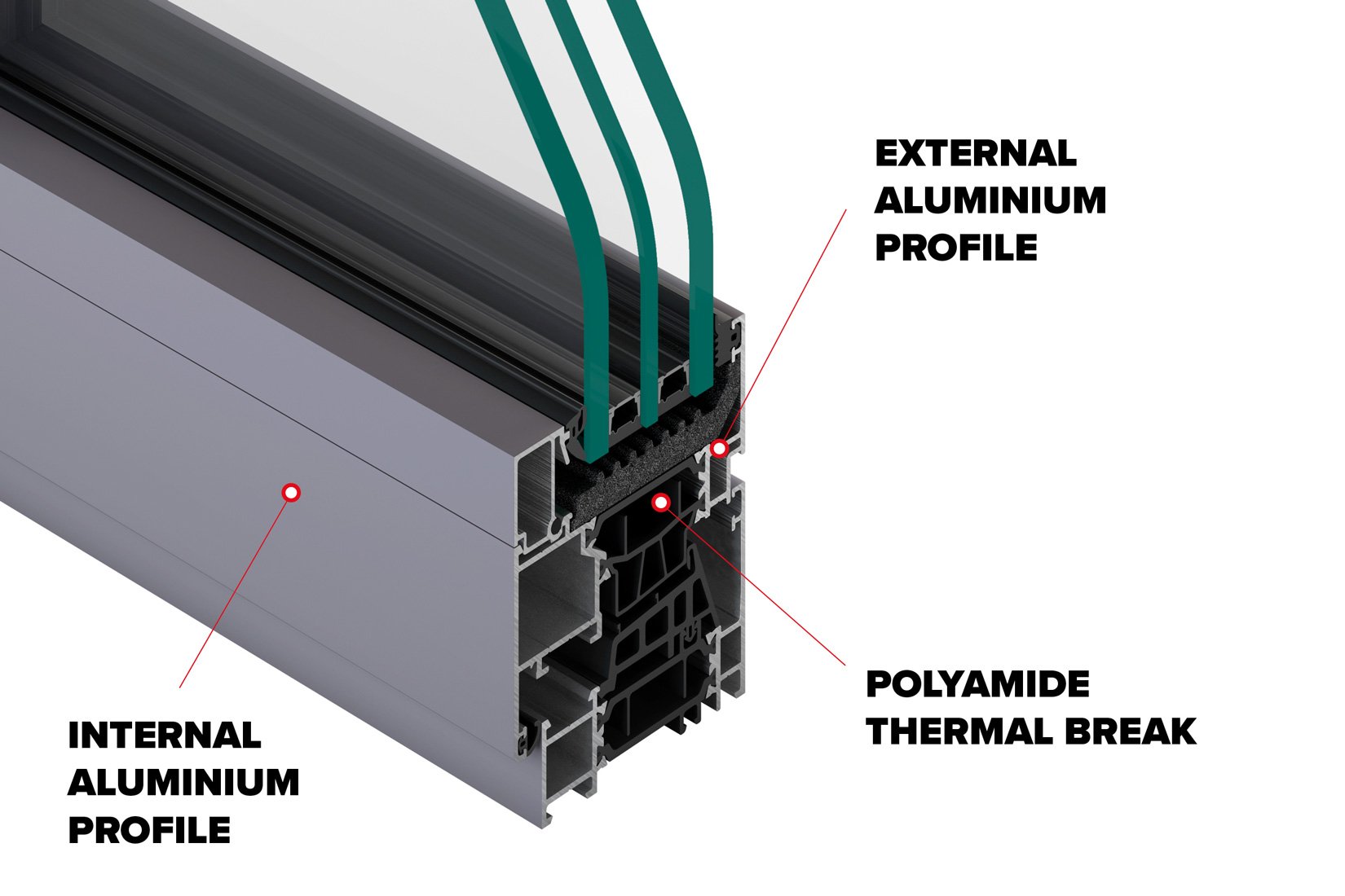
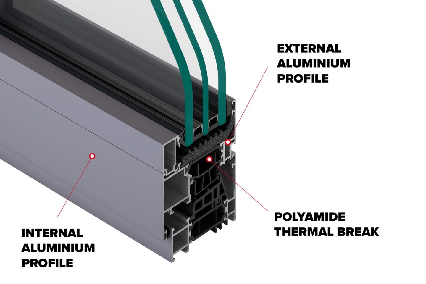
Cross-Section View of Thermal Break Configuration within Aluminum Framing
Climate-Specific Selection: Washington, DC and the Southeast
Glazing selection priorities shift meaningfully across our two primary markets. In the mixed climate of the DC Metro region (ASHRAE Climate Zone 4A), heating and cooling seasons are both consequential: U-factor, SHGC, and condensation resistance all carry weight, and the balance point depends on orientation, glazed area, and interior humidity. In the hot-humid Southeast (Climate Zones 2A and 3A, including Atlanta), the hierarchy is clearer: SHGC control is the dominant energy consideration, spectral selectivity is what makes generous glazing areas viable, and the near-infrared rejection of a high-LSG coating pays for itself in cooling capacity and peak load.
U-factor is not irrelevant in the South – it remains a comfort and code consideration – but the condensation dynamic partially inverts. In air-conditioned buildings in hot-humid climates, the exterior glass surface and the frame can fall below the outdoor dew point, producing exterior condensation – generally a benign curiosity – while the more consequential Southeast moisture risks live elsewhere in the enclosure, in the vapor drive and air leakage mechanisms covered earlier in this series. Both the IECC and ASHRAE 90.1 set fenestration U-factor and SHGC requirements by climate zone, with SHGC requirements tightening toward the South – and, as with opaque assemblies, compliance is demonstrated with rated whole-product values.
Specification and Verification
As with every enclosure system this series has examined, the difference between rated performance and delivered performance is closed through process discipline:
- Specify whole-product NFRC-rated values for U-factor, SHGC, VT, and condensation resistance – and review submittals against them. Center-of-glass values in a submittal are not evidence of compliance.
- Coordinate the glazing makeup with the framing system – coating surface placement, gas fill, spacer type, and frame thermal breaks interact, and the whole-product rating reflects the specific combination, not interchangeable parts.
- Model project-specific conditions where interior humidity, unusual orientations, or high glazed area warrant it, using THERM or equivalent analysis at design interior and exterior conditions.
- Verify in the field. Laboratory mockup testing and field water penetration and air leakage testing per AAMA 501.2 and ASTM protocols confirm installed performance of the fenestration system; infrared thermography after enclosure verifies thermal continuity at the glazing-to-wall transitions where the enclosure’s control layers change hands.
Within a Building Enclosure Commissioning (BECx) program, fenestration receives this scrutiny systematically – from Owner’s Project Requirements (OPR) through design review, submittal review, mockup, field testing, and post-construction verification – rather than episodically.
Why This Matters
For most commercial and multi-family buildings, fenestrations are simultaneously the enclosure’s largest thermal liability and its most visible architectural asset. The technologies examined this month – low-emissivity coatings, spectrally selective transmission, optimized multi-pane assemblies – have transformed what glazed façades can deliver. But that performance is not inherent in the product category; it is the result of specific selections, correctly combined, verified against whole-product ratings, and installed in framing systems that do not undo them.
The consequences of getting it wrong are familiar from every installment of this series: energy performance that falls short of the model, condensation at the coldest surfaces the occupants can see and touch, and comfort complaints concentrated exactly where the building meets its views. The consequences of getting it right are equally tangible – daylight without the cooling penalty, warm interior glass in January, and a fenestration system that performs as the energy model assumed it would.
A glazing schedule is a set of laboratory ratings.
A façade is specific to a climate, orientation, frame, and interior environment.
Performance is decided where the two meet – and so are condensation, comfort, and cooling load.
What’s Next in Enclosure Insights
In the next installment of Enclosure Insights, we continue our examination of fenestration performance by turning from the glazing unit itself to the broader strategies used to control what reaches it: shading and daylighting design. We will examine how building-integrated shading elements – horizontal overhangs, vertical fins, and combined louver systems – intercept direct solar radiation before it reaches the glazing plane, reducing cooling loads and glare without sacrificing daylight quality. We will also discuss how façade orientation fundamentally determines the effectiveness of each shading strategy – and why an overhang optimized for a south-facing elevation offers little benefit on an east or west exposure where low-angle morning and afternoon sun overwhelms fixed shading geometry. Together, radiation-control glazing and passive shading design form a complementary toolkit for managing solar loads at the building enclosure level.
SK&A’s Building Enclosure Consulting + Waterproofing team brings decades of experience and specialized technical expertise to aid in the design and construction of new buildings, as well as the evaluation and maintenance of existing buildings. Learn more.