News + Insights
We’re making news!
Explore project milestones and accolades, structural engineering news and insights, and spotlight moments from our exceptional staff.
Explore project milestones and accolades, structural engineering news and insights, and spotlight moments from our exceptional staff.
Insights
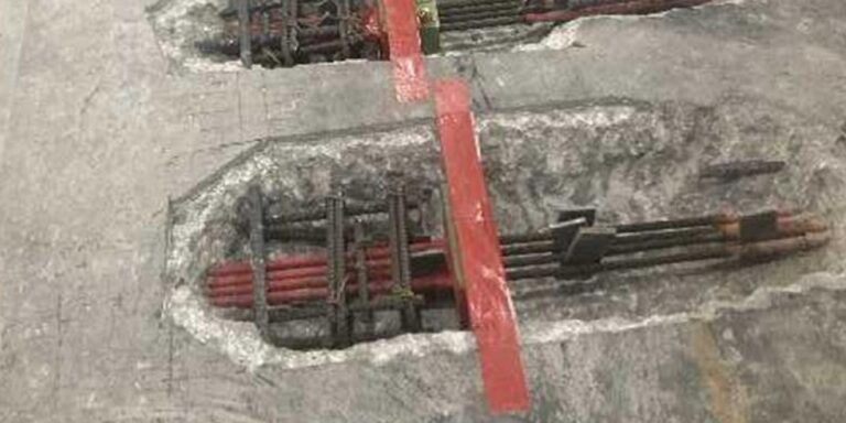
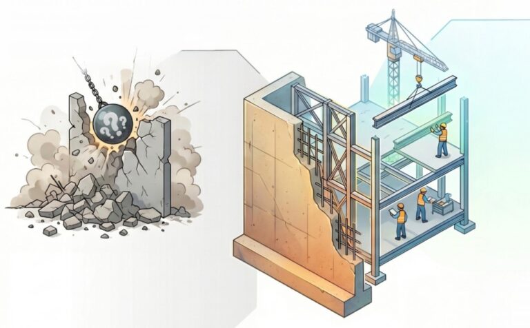
Creating Openings in Existing Post-Tensioned Slabs
June 15, 2026
Project Updates
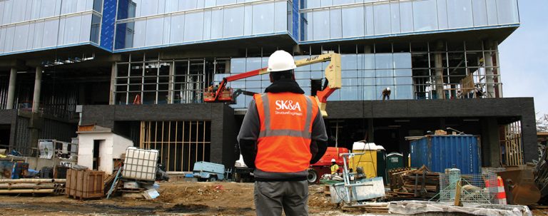
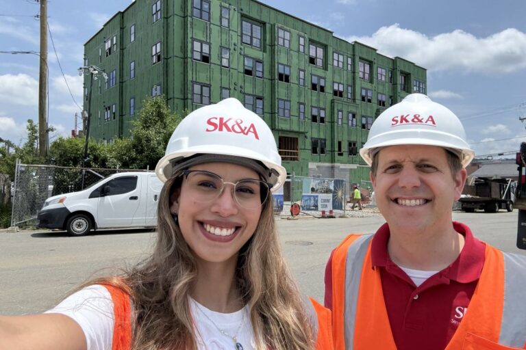
Beacon Landing Tops Out in Fairfax
June 11, 2026
Giving Back
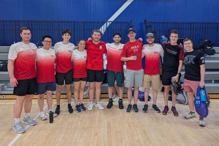
SK&A Competes in 2026 T1D Real Estate Games
June 10, 2026
Awards
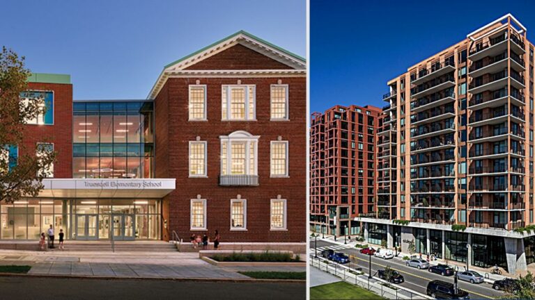
Four SK&A Projects Earn WBC Craftsmanship Awards
June 09, 2026
Insights
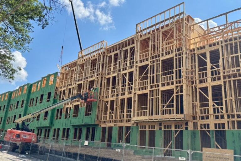
Wood-Framed Balconies in Atlanta
June 09, 2026

Staff Highlights
Celebrating Our 1st Year With Avery Dittmer
June 09, 2026

Staff Highlights
Celebrating 20 Years
With Rony Paredes
June 05, 2026
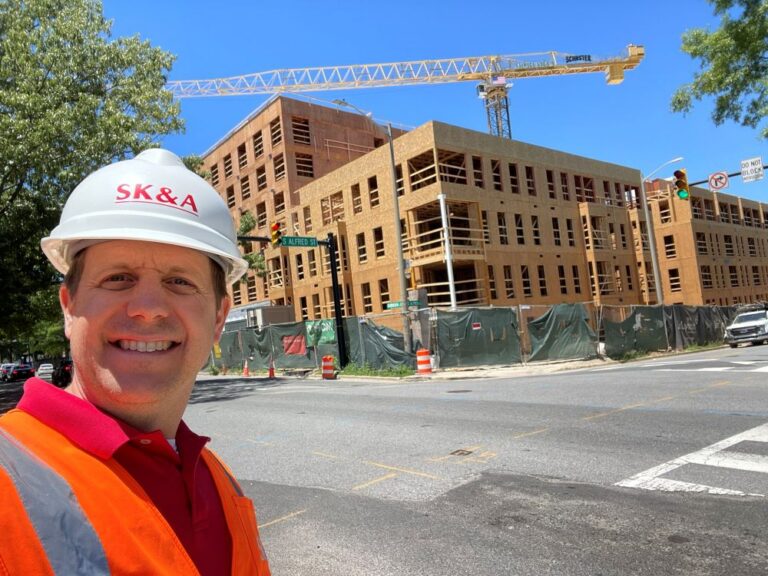
Project Updates
Heritage Old Town Block 4 Tops Out in Alexandria
June 04, 2026
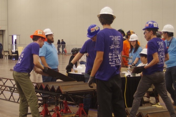
Staff Highlights
SK&A Intern Helps UF Win AISC Steel Bridge Finals
June 03, 2026
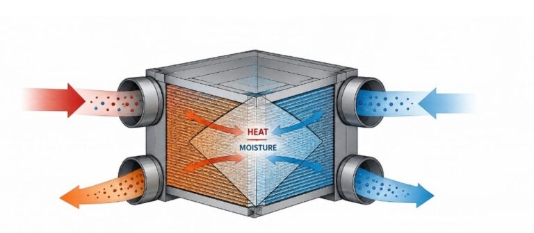
Insights
Enclosure Insights: Enthalpy Recovery Ventilation
June 03, 2026
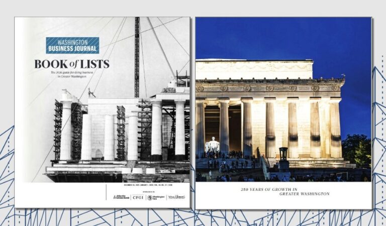
In the News
Thirteen Years on WBJ’s Top Engineering Firms List
May 29, 2026
Insights
Reusing Existing Basement Walls in Adaptive Reuse Projects
May 19, 2026
In the News
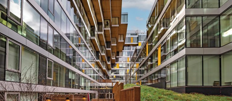
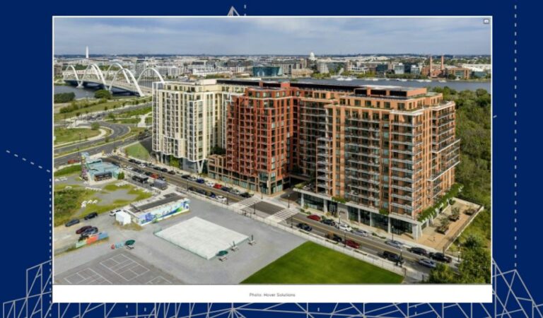
World’s Largest Zero-Carbon-Certified Multifamily Building
May 13, 2026

Awards
Annex on 12th and The Wendy Receive ULI Awards
May 08, 2026
In the News
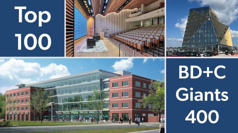
SK&A Among Nation’s Top University Building Engineers
May 06, 2026
Insights
Enclosure Insights: Air Control
May 06, 2026